Menu
Wiring Diagram
Dimensions and Wiring Instructions
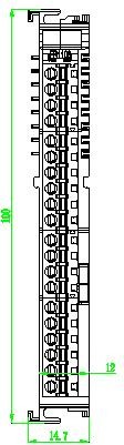
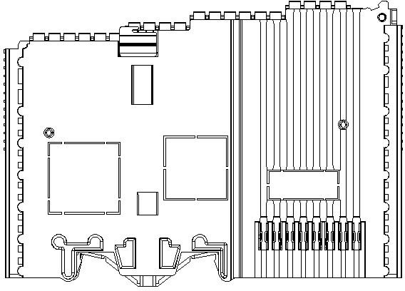
SRT5032 Module Dimension Diagram
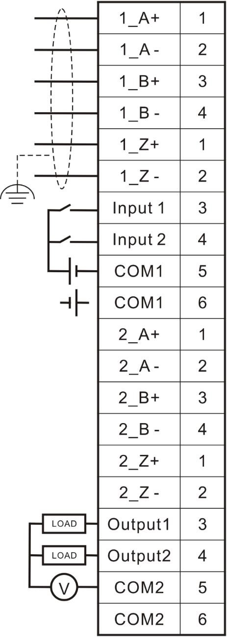
SRT5032 Module Wiring Table
| Terminal No. | Identification | Description |
|---|---|---|
| IN A1+ | 1 | Positive pole of CH1 encoder phase A |
| IN A1- | 2 | Negative pole of CH1 encoder phase A |
| IN B1+ | 3 | Positive pole of CH1 encoder phase B |
| IN B1- | 4 | Negative pole of CH1 encoder phase B |
| IN Z1+ | 1 | Positive pole of CH1 encoder phase Z |
| IN Z1- | 2 | Negative pole of CH1 encoder phase Z |
| INPUT 1 | 3 | Input for CH1 |
| INPUT 2 | 4 | Input for CH2 |
| COM1 | 5 | Common terminal for input |
| COM1 | 6 | Common terminal for input |
| IN A2+ | 1 | Positive pole of CH2 encoder phase A |
| IN A2- | 2 | Negative pole of CH2 encoder phase A |
| IN B2+ | 3 | Positive pole of CH2 encoder phase B |
| IN B2- | 4 | Negative pole of CH2 encoder phase B |
| IN Z2+ | 1 | Positive pole of CH2 encoder phase Z |
| IN Z2- | 2 | Negative pole of CH2 encoder phase Z |
| OUTPUT 1 | 3 | Output for CH1 |
| OUTPUT 2 | 4 | Output for CH2 |
| COM2 | 5 | Common terminal for output |
| COM2 | 6 | Common terminal for output |
Note: The two COM1s at the input common terminal are internally short-circuited, i.e. the input signal type of CH1 and CH2 shall be PNP or NPN; The two COM2s at relay output common terminal are internally short-circuited, i.e. the input signal type of CH1 and CH2 shall be the same.
Share this Article
Last modified: 2025-06-30
- MetaOS Overview
- How to log in and view the system
- How to modify the system language
- How to set network port IP using command line method
- How to set real-time domain system time, non real time domain system time, and hardware time
- How to check the status of PLC
- How to check the status of system resources
- How to view system logs
- How to set system memory
- How to allocate system CPU
- How to allocate system network ports
- How to use the command line to set NIC interrupts
- Chapter 1: Installation and Uninstallation
- Chapter 2: Set the user interface language to Simplified Chinese
- Chapter 3: New Construction
- Chapter 4: Open Project
- Chapter 5: Add / Delete / Export Devices
- Chapter 6: Connecting to PLC
- Chapter 7: Connecting MetaFacture PLC Simulator
- Chapter 8: Downloading and Uploading Projects
- Chapter 9: Scanning Devices
- Chapter 10: Installing and Using Libraries
- Safety tips for unpacking acceptance
- Safety tips for storage and transport
- Safety tips during assembly
- Safety tips for equipment wiring
- Safety tips for equipment power-on
- Safety tips for equipment operation
- Safety tips for equipment maintenance
- Safety tips for equipment repair
- Safety tips for equipment recycling
- Technical Specifications
- Troubleshooting and Disposal
- Expansion Module
- Appendix
- Safety tips for unpacking acceptance
- Safety tips for storage and transport
- Safety tips during assembly
- Safety tips for equipment wiring
- Safety tips for equipment power-on
- Safety tips for equipment operation
- Safety tips for equipment maintenance
- Safety tips for equipment repair
- Safety tips for equipment recycling
- Product overview
- Technical Specifications
- Troubleshooting and Disposal
- Care and Maintenance
- Appendix
- Safety tips for unpacking acceptance
- Safety tips for storage and transport
- Safety tips during assembly
- Safety tips for equipment wiring
- Safety tips for equipment power-on
- Safety tips for equipment operation
- Safety tips for equipment maintenance
- Safety tips for equipment repair
- Safety tips for equipment recycling
- Object Dictionary
- SV35 Profinet Series AC Servo Driver
- Safety tips for unpacking acceptance
- Safety tips for storage and transport
- Safety tips during assembly
- Safety tips for equipment wiring
- Safety tips for equipment power-on
- Safety tips for equipment operation
- Safety tips for equipment maintenance
- Safety tips for equipment repair
- Safety tips for equipment recycling
- Product Overview
- Technical Specifications
- Motor