Wiring Diagram
Dimensions and Wiring Descriptions of SRT2X16
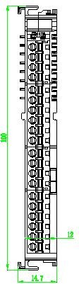
SRT2X16 Module Dimension Diagram
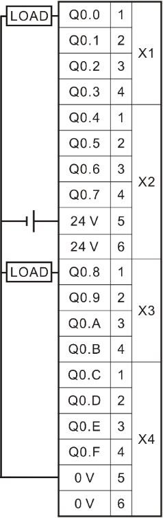
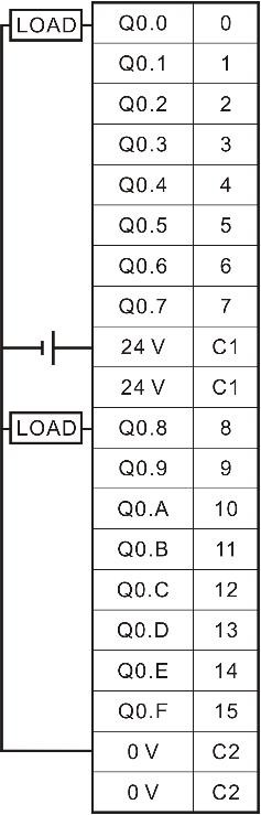
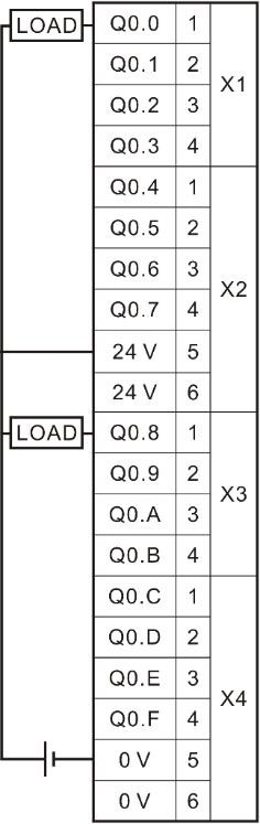
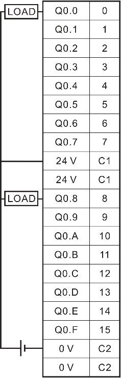
SRT2X16 Module Wiring Diagram (Upper SRT2116, Lower SRT2216; There are two versions of terminal silkscreen identification for different batches, which do not affect the use)
SRT2X16 Module Wiring Table
| Output Point | Terminal Silkscreen Identification (Version A) | Terminal Silkscreen Identification (Version B) | Description |
|---|---|---|---|
| Q 0.0 | 1 | 0 | Output Channel 0 |
| Q 0.1 | 2 | 1 | Output Channel 1 |
| Q 0.2 | 3 | 2 | Output Channel 2 |
| Q 0.3 | 4 | 3 | Output Channel 3 |
| Q 0.4 | 1 | 4 | Output Channel 4 |
| Q 0.5 | 2 | 5 | Output Channel 5 |
| Q 0.6 | 3 | 6 | Output Channel 6 |
| Q 0.7 | 4 | 7 | Output Channel 7 |
| 24V | 5& 6 | C1 | 24V Common Terminal |
| Q 0.8 | 1 | 8 | Output Channel 8 |
| Q 0.9 | 2 | 9 | Output Channel 9 |
| Q 0.A | 3 | 10 | Output Channel 10 |
| Q 0.B | 4 | 11 | Output Channel 11 |
| Q 0.C | 1 | 12 | Output Channel 12 |
| Q 0.D | 2 | 13 | Output Channel 13 |
| Q 0.E | 3 | 14 | Output Channel 14 |
| Q 0.F | 4 | 15 | Output Channel 15 |
| 0V | 5& 6 | C2 | 0V Common Terminal |
SRT2X16 Wiring Instructions:
Terminal 5 or 6 of wiring terminal X2 in digital output module SRT2X16 is connected with 24V, and terminal 5 or 6 of wiring terminal X4 is connected with 0V. Each group of 24V is provided with two wiring terminals. The module has been connected internally, which is convenient for users to use in parallel.
Dimensions and Wiring Descriptions of SRT2X32
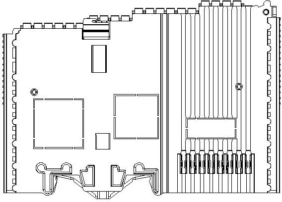
SRT2X32 Module Dimension Diagram
SRT2X32 Module Wiring Diagram (Upper SRT2132, Lower SRT2232; There are two versions of terminal silkscreen identification in different batches, which do not affect the use. Note that the left and right sides of 32DO module fixed together need to be connected with 24V and 0V, and the wiring diagram is simplified for beautiful appearance)
SRT2X16 Module Wiring Table
| Output Point | Description | Output Point | Description |
|---|---|---|---|
| Q 0.0 | Output Channel 0 | Q 1.0 | Output Channel 16 |
| Q 0.1 | Output Channel 1 | Q 1.1 | Output Channel 17 |
| Q 0.2 | Output Channel 2 | Q 1.2 | Output Channel 18 |
| Q 0.3 | Output Channel 3 | Q 1.3 | Output Channel 19 |
| Q 0.4 | Output Channel 4 | Q 1.4 | Output Channel 20 |
| Q 0.5 | Output Channel 5 | Q 1.5 | Output Channel 21 |
| Q 0.6 | Output Channel 6 | Q 1.6 | Output Channel 22 |
| Q 0.7 | Output Channel 7 | Q 1.7 | Output Channel 23 |
| 24V | 24V | 24V | 24V |
| Q 0.8 | Output Channel 8 | Q 1.8 | Output Channel 24 |
| Q 0.9 | Output Channel 9 | Q 1.9 | Output Channel 25 |
| Q 0.A | Output Channel 10 | Q 1.A | Output Channel 26 |
| Q 0.B | Output Channel 11 | Q 1.B | Output Channel 27 |
| Q 0.C | Output Channel 12 | Q 1.C | Output Channel 28 |
| Q 0.D | Output Channel 13 | Q 1.D | Output Channel 29 |
| Q 0.E | Output Channel 14 | Q 1.E | Output Channel 30 |
| Q 0.F | Output Channel 15 | Q 1.F | Output Channel 31 |
| 0V | 0V | 0V | 0V |
SRT2X32 Wiring Instructions:
Terminal 5 or 6 of wiring terminal X2 in digital output module SRT2X32 is connected with 24V, and terminal 5 or 6 of wiring terminal X4 is connected with 0V. For the 32-channel DO module, both left and right adjacent modules must be connected to 24V and 0V. Each 24V power group provides two terminals internally connected, allowing users to parallel wires conveniently.
- MetaOS Overview
- How to log in and view the system
- How to modify the system language
- How to set network port IP using command line method
- How to set real-time domain system time, non real time domain system time, and hardware time
- How to check the status of PLC
- How to check the status of system resources
- How to view system logs
- How to set system memory
- How to allocate system CPU
- How to allocate system network ports
- How to use the command line to set NIC interrupts
- Chapter 1: Installation and Uninstallation
- Chapter 2: Set the user interface language to Simplified Chinese
- Chapter 3: New Construction
- Chapter 4: Open Project
- Chapter 5: Add / Delete / Export Devices
- Chapter 6: Connecting to PLC
- Chapter 7: Connecting MetaFacture PLC Simulator
- Chapter 8: Downloading and Uploading Projects
- Chapter 9: Scanning Devices
- Chapter 10: Installing and Using Libraries
- Safety tips for unpacking acceptance
- Safety tips for storage and transport
- Safety tips during assembly
- Safety tips for equipment wiring
- Safety tips for equipment power-on
- Safety tips for equipment operation
- Safety tips for equipment maintenance
- Safety tips for equipment repair
- Safety tips for equipment recycling
- Technical Specifications
- Troubleshooting and Disposal
- Expansion Module
- Appendix
- Safety tips for unpacking acceptance
- Safety tips for storage and transport
- Safety tips during assembly
- Safety tips for equipment wiring
- Safety tips for equipment power-on
- Safety tips for equipment operation
- Safety tips for equipment maintenance
- Safety tips for equipment repair
- Safety tips for equipment recycling
- Product overview
- Technical Specifications
- Troubleshooting and Disposal
- Care and Maintenance
- Appendix
- Safety tips for unpacking acceptance
- Safety tips for storage and transport
- Safety tips during assembly
- Safety tips for equipment wiring
- Safety tips for equipment power-on
- Safety tips for equipment operation
- Safety tips for equipment maintenance
- Safety tips for equipment repair
- Safety tips for equipment recycling
- Object Dictionary
- SV35 Profinet Series AC Servo Driver
- Safety tips for unpacking acceptance
- Safety tips for storage and transport
- Safety tips during assembly
- Safety tips for equipment wiring
- Safety tips for equipment power-on
- Safety tips for equipment operation
- Safety tips for equipment maintenance
- Safety tips for equipment repair
- Safety tips for equipment recycling
- Product Overview
- Technical Specifications
- Motor