Menu
Wiring Diagram
Dimensions and Wiring Instructions
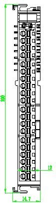
SRT3028 Module Dimension Diagram
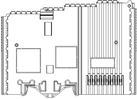
SRT3028 Module Wiring Diagram
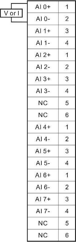
SRT3028 Module Wiring Table
| Input Channel Definition | Terminal Silkscreen Identification | External Wiring Description |
|---|---|---|
| AI 0+ | 1 | Input Channel 0 Positive pole |
| AI 0- | 2 | Input Channel 0 Negative pole |
| AI 1+ | 3 | Input Channel 1 Positive pole |
| AI 1- | 4 | Input Channel 1 Negative pole |
| AI 2+ | 1 | Input Channel 2 Positive pole |
| AI 2- | 2 | Input Channel 2 Negative pole |
| AI 3+ | 3 | Input Channel 3 Positive pole |
| AI 3- | 4 | Input Channel 3 Negative pole |
| NC | 5& 6 | No wiring required |
| AI 4+ | 1 | Input Channel 4 Positive pole |
| AI 4- | 2 | Input Channel 4 Negative pole |
| AI 5+ | 3 | Input Channel 5 Positive pole |
| AI 5- | 4 | Input Channel 5 Negative pole |
| AI 6+ | 1 | Input Channel 6 Positive pole |
| AI 6- | 2 | Input Channel 6 Negative pole |
| AI 7+ | 3 | Input Channel 7 Positive pole |
| AI 7- | 4 | Input Channel 7 Negative pole |
| NC | 5& 6 | No wiring required |
Share this Article
Previous
Indicator Description
Next
SRT3182|High-speed analog input Module
Last modified: 2025-06-30
- MetaOS Overview
- How to log in and view the system
- How to modify the system language
- How to set network port IP using command line method
- How to set real-time domain system time, non real time domain system time, and hardware time
- How to check the status of PLC
- How to check the status of system resources
- How to view system logs
- How to set system memory
- How to allocate system CPU
- How to allocate system network ports
- How to use the command line to set NIC interrupts
- Chapter 1: Installation and Uninstallation
- Chapter 2: Set the user interface language to Simplified Chinese
- Chapter 3: New Construction
- Chapter 4: Open Project
- Chapter 5: Add / Delete / Export Devices
- Chapter 6: Connecting to PLC
- Chapter 7: Connecting MetaFacture PLC Simulator
- Chapter 8: Downloading and Uploading Projects
- Chapter 9: Scanning Devices
- Chapter 10: Installing and Using Libraries
- Safety tips for unpacking acceptance
- Safety tips for storage and transport
- Safety tips during assembly
- Safety tips for equipment wiring
- Safety tips for equipment power-on
- Safety tips for equipment operation
- Safety tips for equipment maintenance
- Safety tips for equipment repair
- Safety tips for equipment recycling
- Technical Specifications
- Troubleshooting and Disposal
- Expansion Module
- Appendix
- Safety tips for unpacking acceptance
- Safety tips for storage and transport
- Safety tips during assembly
- Safety tips for equipment wiring
- Safety tips for equipment power-on
- Safety tips for equipment operation
- Safety tips for equipment maintenance
- Safety tips for equipment repair
- Safety tips for equipment recycling
- Product overview
- Technical Specifications
- Troubleshooting and Disposal
- Care and Maintenance
- Appendix
- Safety tips for unpacking acceptance
- Safety tips for storage and transport
- Safety tips during assembly
- Safety tips for equipment wiring
- Safety tips for equipment power-on
- Safety tips for equipment operation
- Safety tips for equipment maintenance
- Safety tips for equipment repair
- Safety tips for equipment recycling
- Object Dictionary
- SV35 Profinet Series AC Servo Driver
- Safety tips for unpacking acceptance
- Safety tips for storage and transport
- Safety tips during assembly
- Safety tips for equipment wiring
- Safety tips for equipment power-on
- Safety tips for equipment operation
- Safety tips for equipment maintenance
- Safety tips for equipment repair
- Safety tips for equipment recycling
- Product Overview
- Technical Specifications
- Motor