HyperCare 2.1.4.0
Ⅰ.Overview
HyperCare(Previous Name:SF8010 Device Manager) is a device management tool software product designed for managing the entire iComputer system, including system information management, hardware information reading and secondary allocation functions. This manual primarily introduces the functions and basic usage methods of each module in SF8010. The following table provides an overview of each product component
| Product components | Description |
|---|---|
| sf8010 basic module (core module) | sf8010 is the core component of the SF8010 device management tool, responsible for the comprehensive management of the iComputer system. It can monitor the operating status of the device and manage hardware resources. This component provides extensive system and hardware information reading functions, supports user reconfiguration through graphical interfaces or command lines, and ensures that the device always operates in optimal conditions. |
| libacp dependency module | libacp is a library file that provides the Access Control Protocol (ACP) function. It supports data encryption, security authentication, and access control. This component is typically used to ensure secure data exchange between devices and systems, preventing unauthorized access. |
| adi-service dependency module | adi-service is the service component of the device interface, primarily used for driving and managing hardware devices. It handles device initialization, configuration, and data transmission while providing connection and communication services with other system components. This component automatically loads and runs during system startup to ensure proper collaboration between the hardware device and the operating system. |
| aoiservice dependency module | aoiservice is an automated operation interface service that provides functions for automatic configuration, monitoring, and management of the device. It can automatically execute operations based on preset conditions, diagnose device issues, or provide relevant logs when failures occur. This component is particularly important for large-scale device management, and it can improve work efficiency and reduce manual intervention. |
Ⅱ.Installation and Uninstallation
1.Software Download
Please download the latest version of the file (the actual version provided by the website shall prevail) from Sinsegye Onlinehelp. The included file list is as follows: (The document version may be newer than those listed below.)
- libacp_0.2.3_amd64.deb
- aoiservice_1.0.6_amd64.deb
- adi-service-full_1.5.1_amd64.deb
- sf8010_2.1.4.0_amd64.deb
2.Installation Process
The following is an example of installing a certain version. After running the second "sudo dpkg -i", install all dependency modules in the sequence listed above.
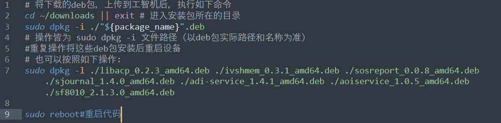
# Copy the downloaded deb files to iComputer downlods directory, then do as following:
cd ~/downloads
sudo dpkg -i ./{package_name}.deb
# The operations are all sudo dpkg -i <filename with full path>
# Once all these debs installed, reboot the iComputer
# can also do like this
# sudo dpkg -l ./libacp_0.2.3_amd64.deb ./ivshmem_0.3.1_amd64.deb ./sosreport_0.0.8_amd64.deb ./sjournal_1.4.0_amd64.deb ./adi-service_1.4.1_amd64.deb ./aoiservice_1.0.5_amd64.deb ./sf8010_2.1.3.0_amd64.deb
sudo reboot #reboot the iComputer
Installation sequence: Install 8010 in the end.
Update and Installation
The process for updates and installations is the same. The new version will automatically overwrite the old version.
Ⅲ.Function Introduction
1. Login
Open the browser, enter the IP address of the iComputer + \[:8010], and then press the \[Enter] key. The page jumps to the login interface of HyperCare.
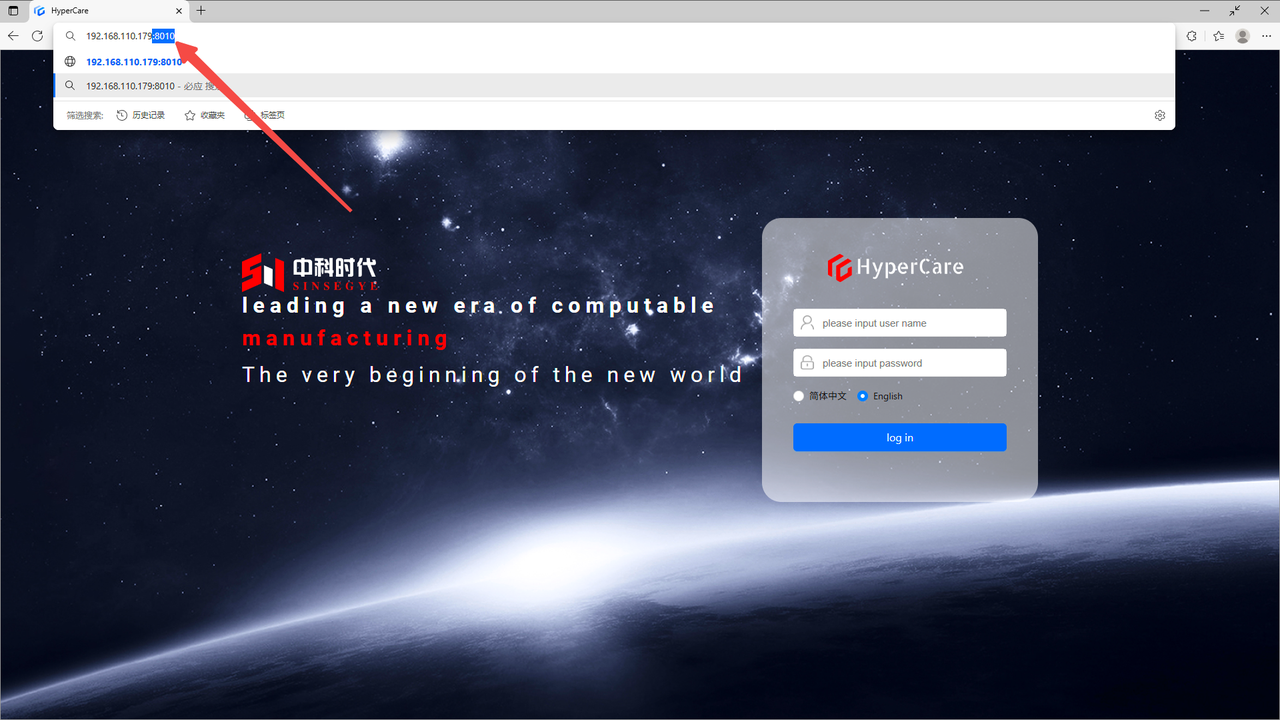
On the login page, enter your \[Username] and \[Password], and then click the \[Login] button.

| Tip: Please keep sensitive information such as username and password safe. For relevant support, please see the "Support and Services for Sinsegye Products" section at the end of the document. |
|---|
2. Device Overview
2.1 Scope of Application
It is applicable to all adapted models.
2.2.Function Introduction
This page displays basic information, software information, and real-time and non-real-time domain information of the real-time monitoring device.
2.3. Usage Details
2.3.1 Enter the page
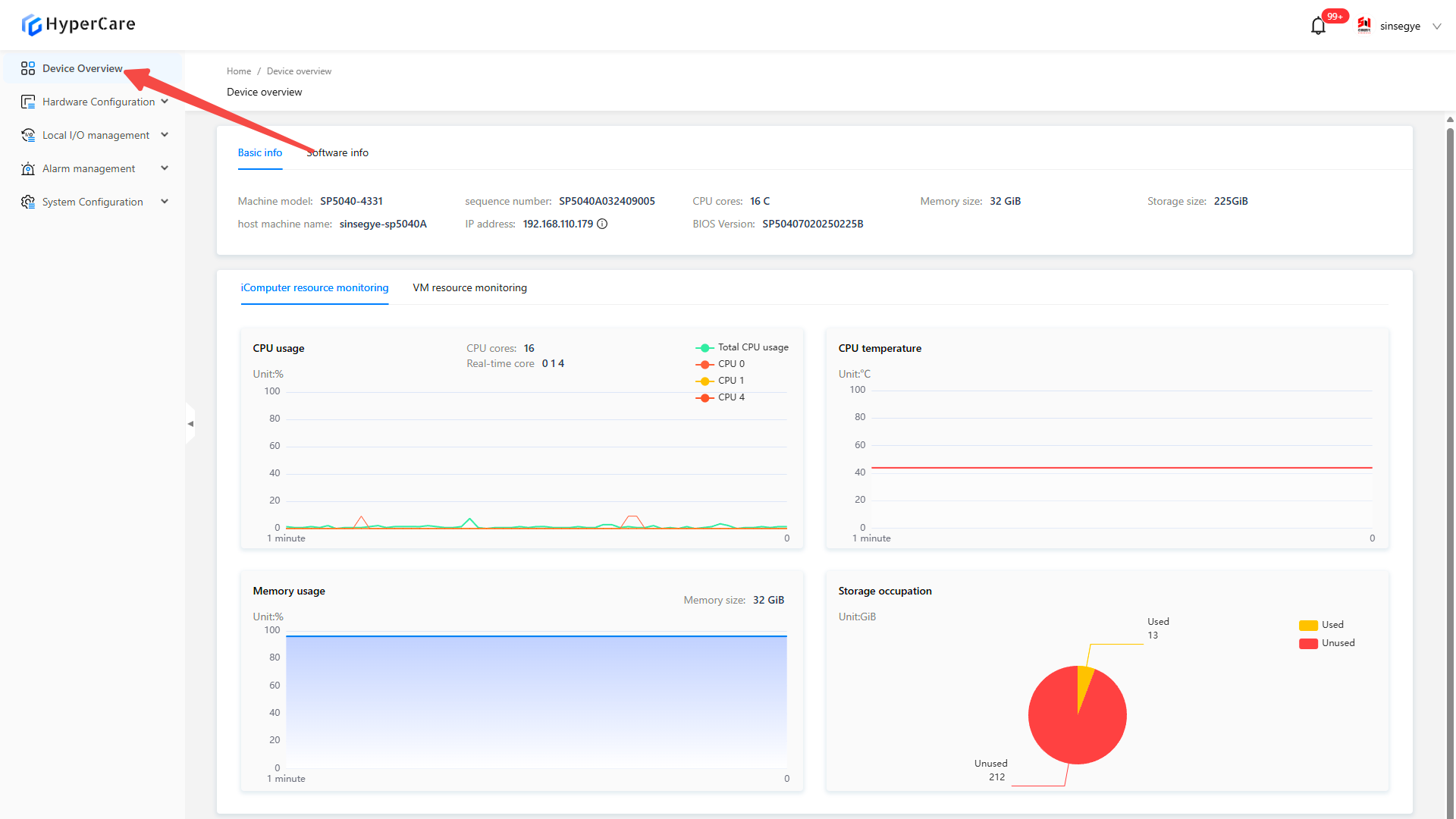
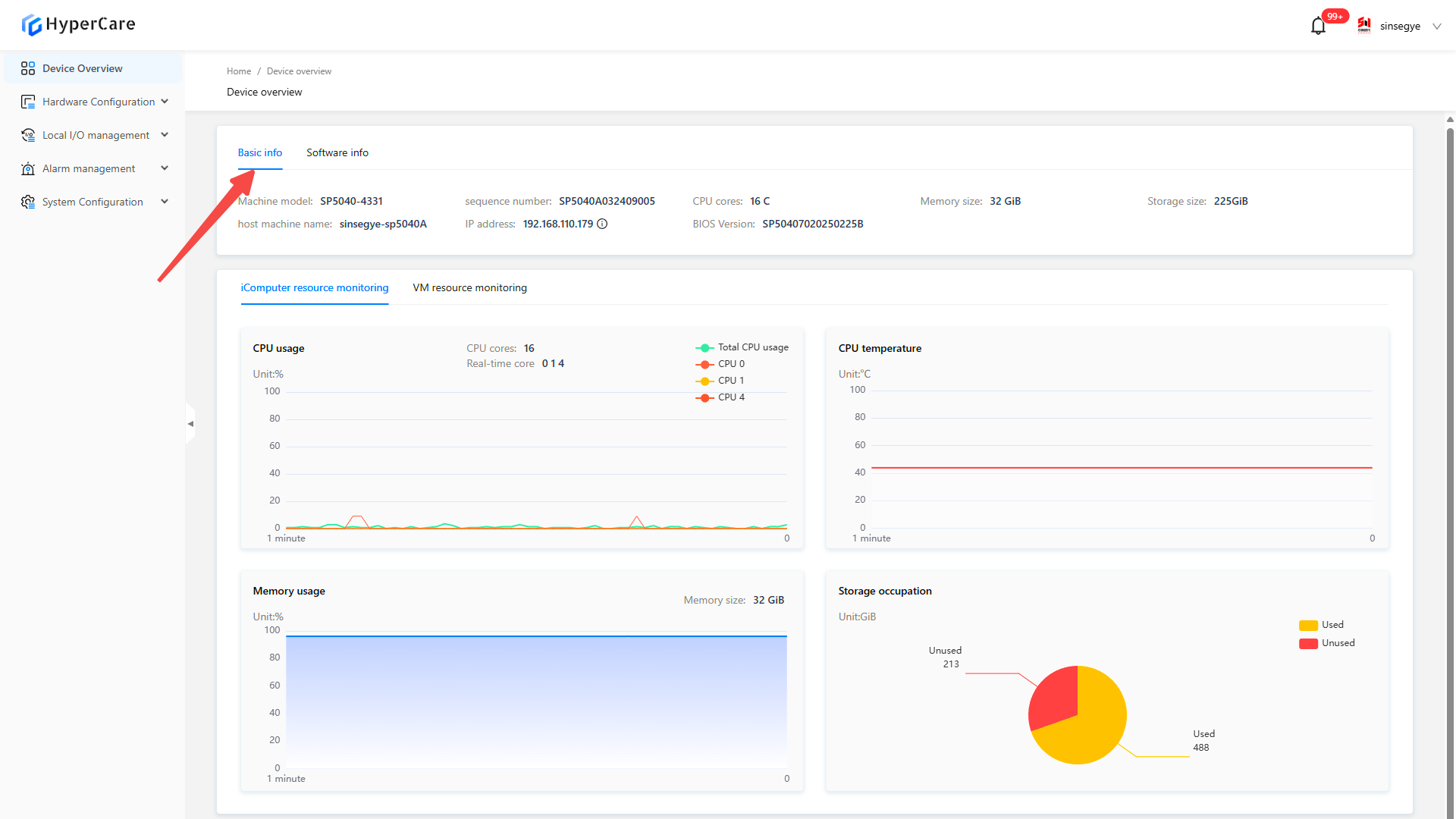
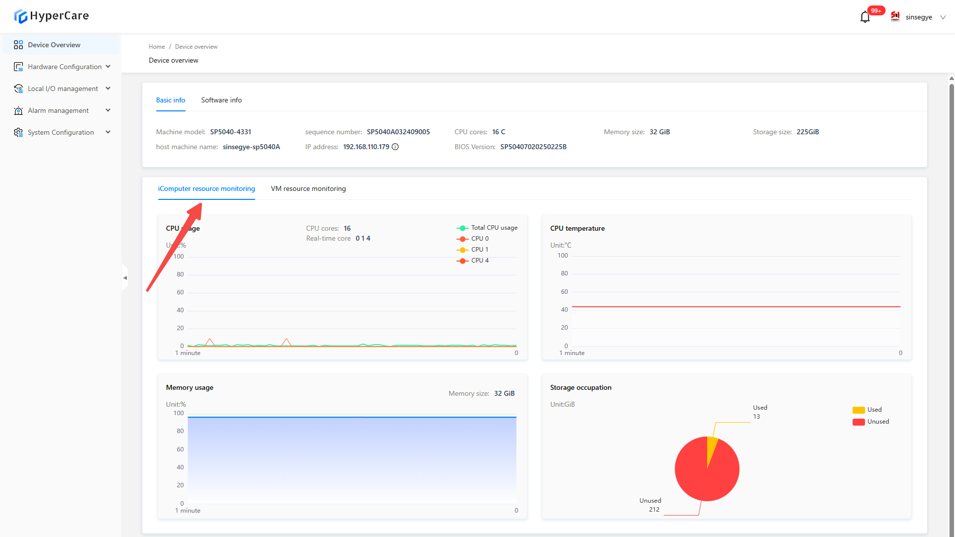
2.3.2 Basic information
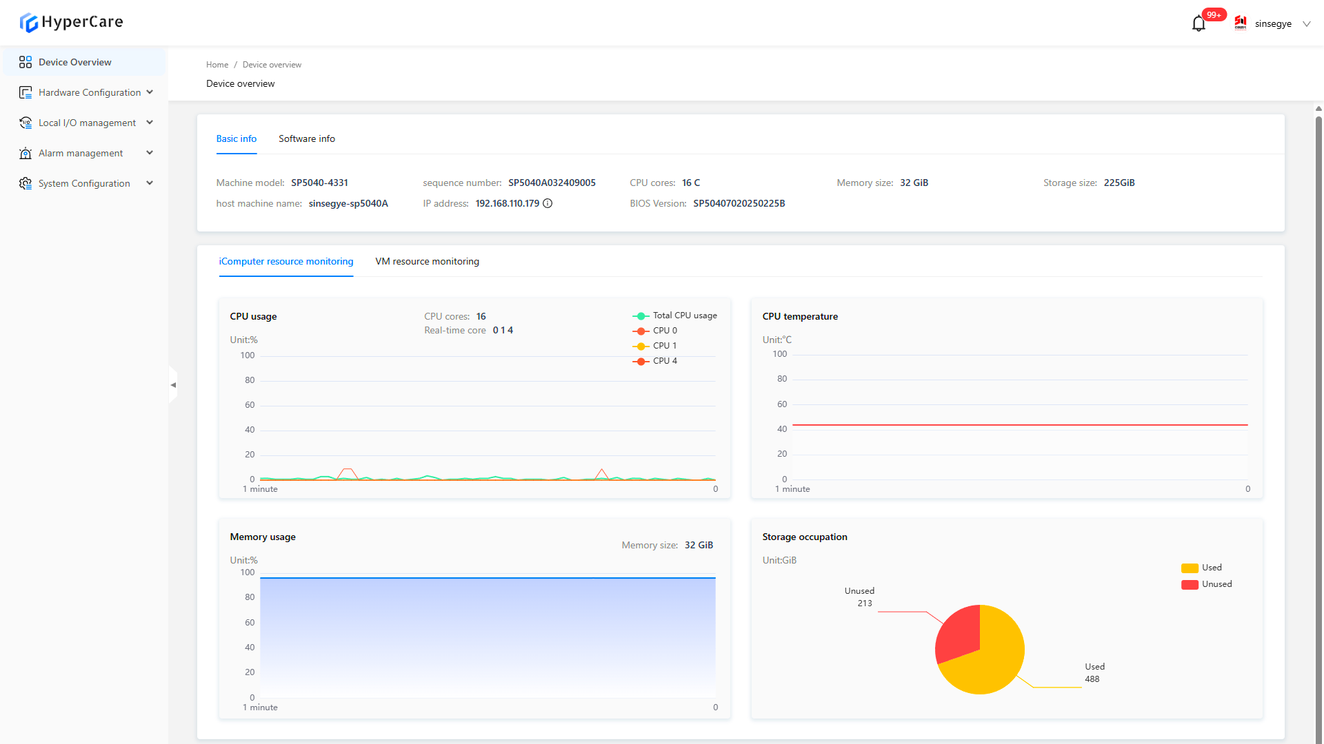
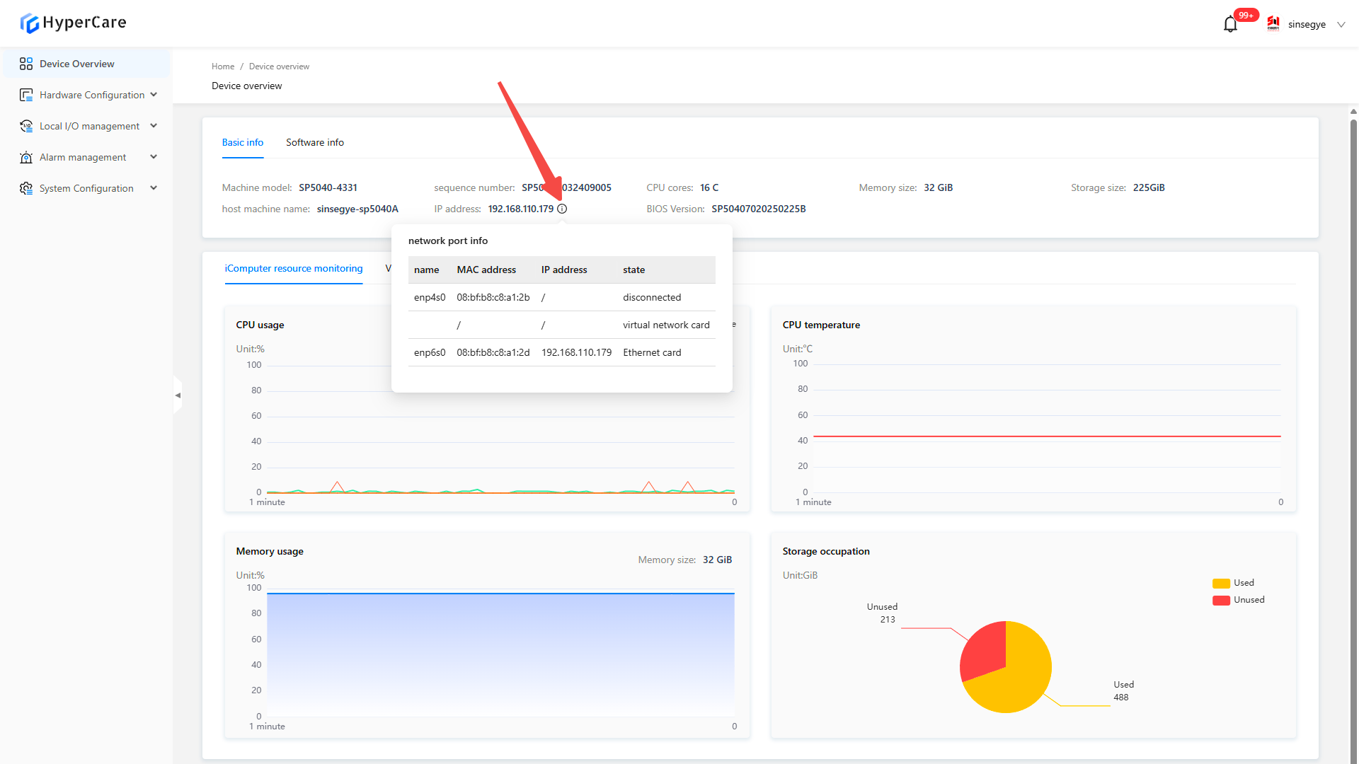
It displays the host's machine model, serial number, number of CPU cores, memory size, storage capacity, host name, IP address, BIOS version, and Cmos battery voltage. Hover the mouse over the \[i] icon to view the detailed information.
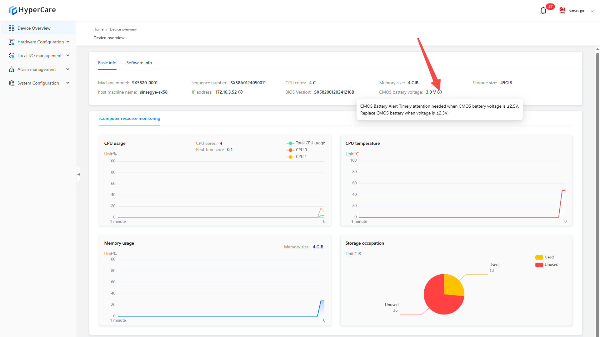
| Cmos battery voltage is only displayed for SX5820-0001 and SX5820-0002. |
|---|
2.3.3 Software information
It displays the software information of the device, including OS version, SF8010 version, RTE version, ACP version, ADI version, and AOI version.
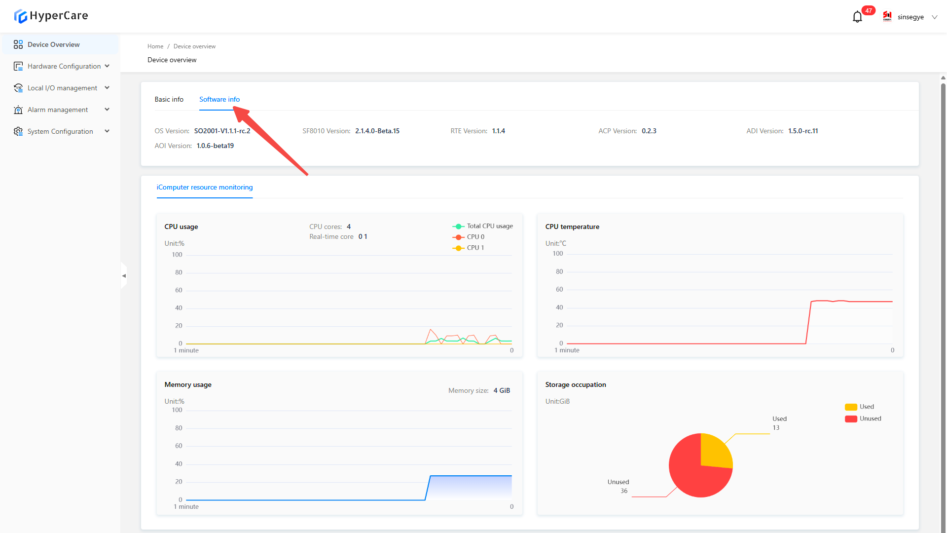
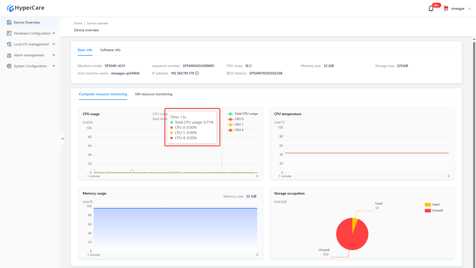
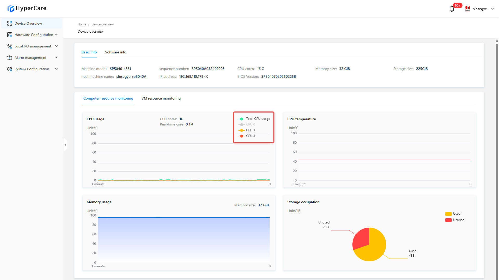
2.3.4 iComputer resource monitoring
The chart displays the CPU usage, temperature, memory usage and storage occupation of the real-time domain.
Hover the mouse over the chart to display the detailed information.
Click the CPU usage to select the displayed information.
2.3.5 Virtual machine resource monitoring:
The chart displays the CPU usage, memory usage, and storage occupancy of the non-real-time domain.
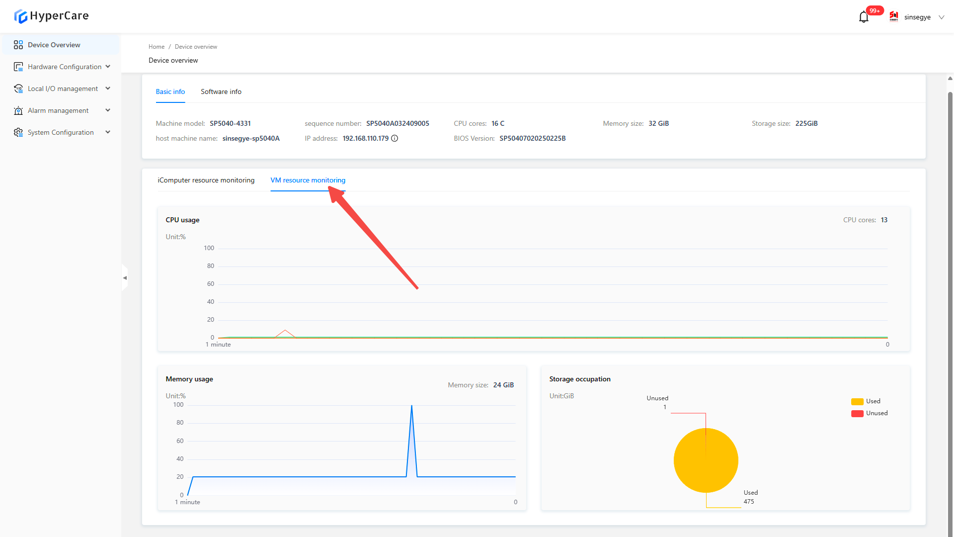
Hover the mouse over the chart to display the detailed information.
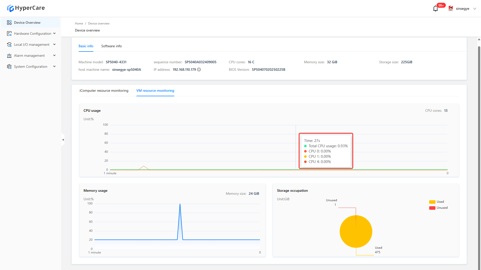
| Only models SP7010-1211, SP7020-2231, SP7022-2231, SP5040-4331, SP5040-3331, SX5232-2112, and SX2133 Type II are equipped with the virtual machine resource monitoring module. |
|---|
3. Hardware Configuration - Network Port Configuration
3.1. Scope of Application
It is applicable to all adapted models.
3.2 Function Introduction
This page displays network interface card (NIC) information in real-time domains and supports custom configurations such as EtherCAT, IP, DNS, and routing for NIC.

3.3 Usage Details
3.3.1 Enter the page
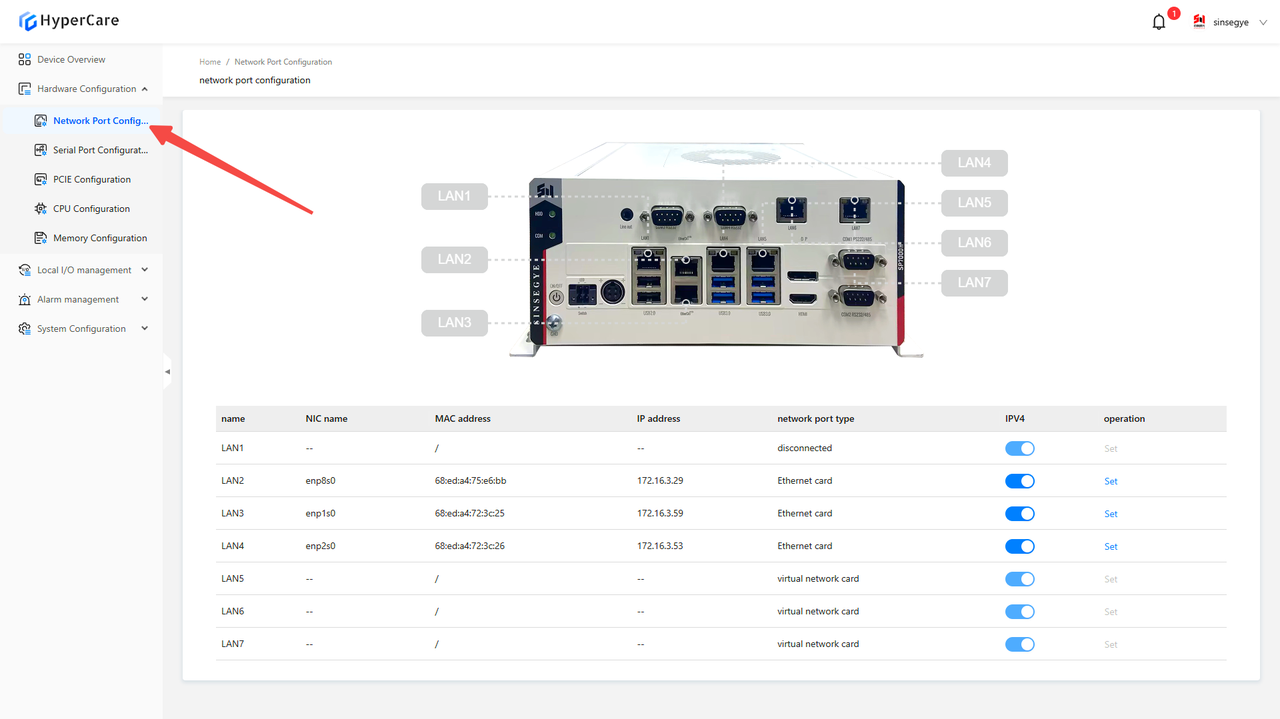
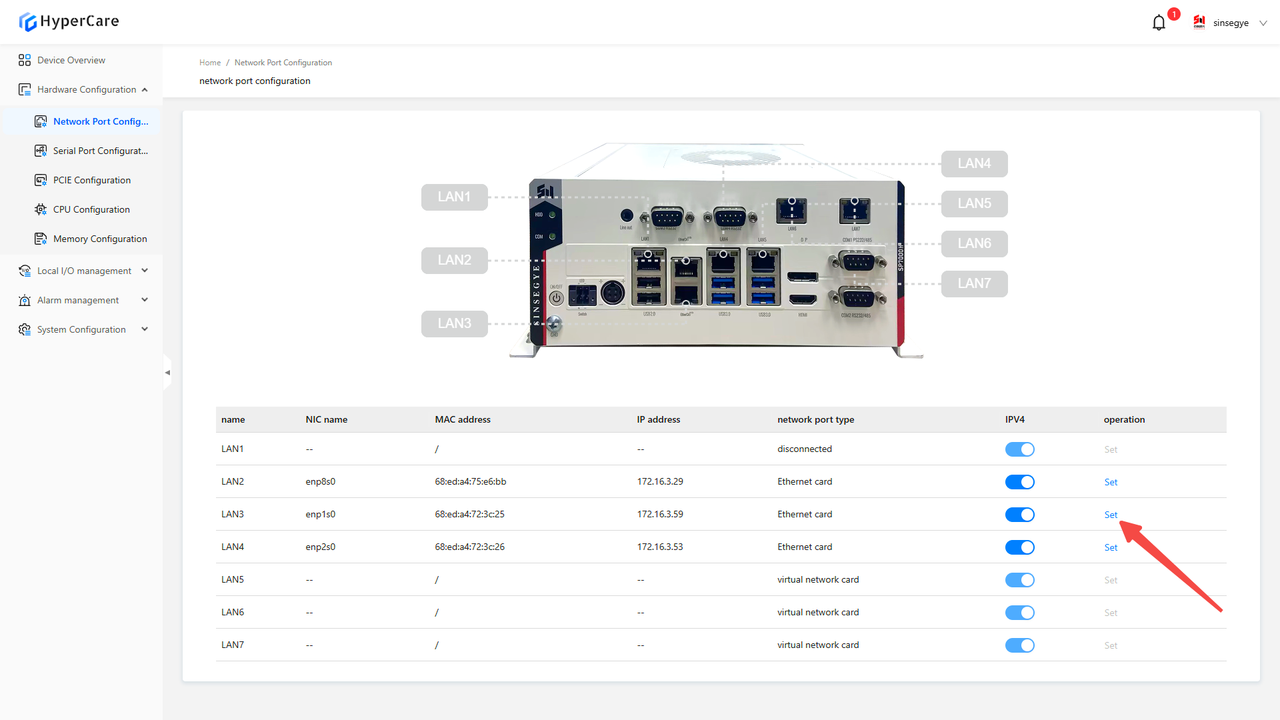
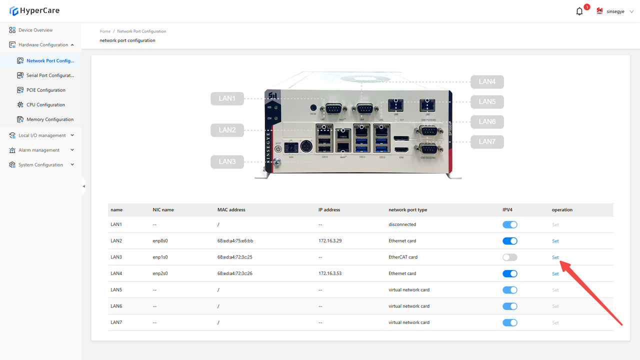
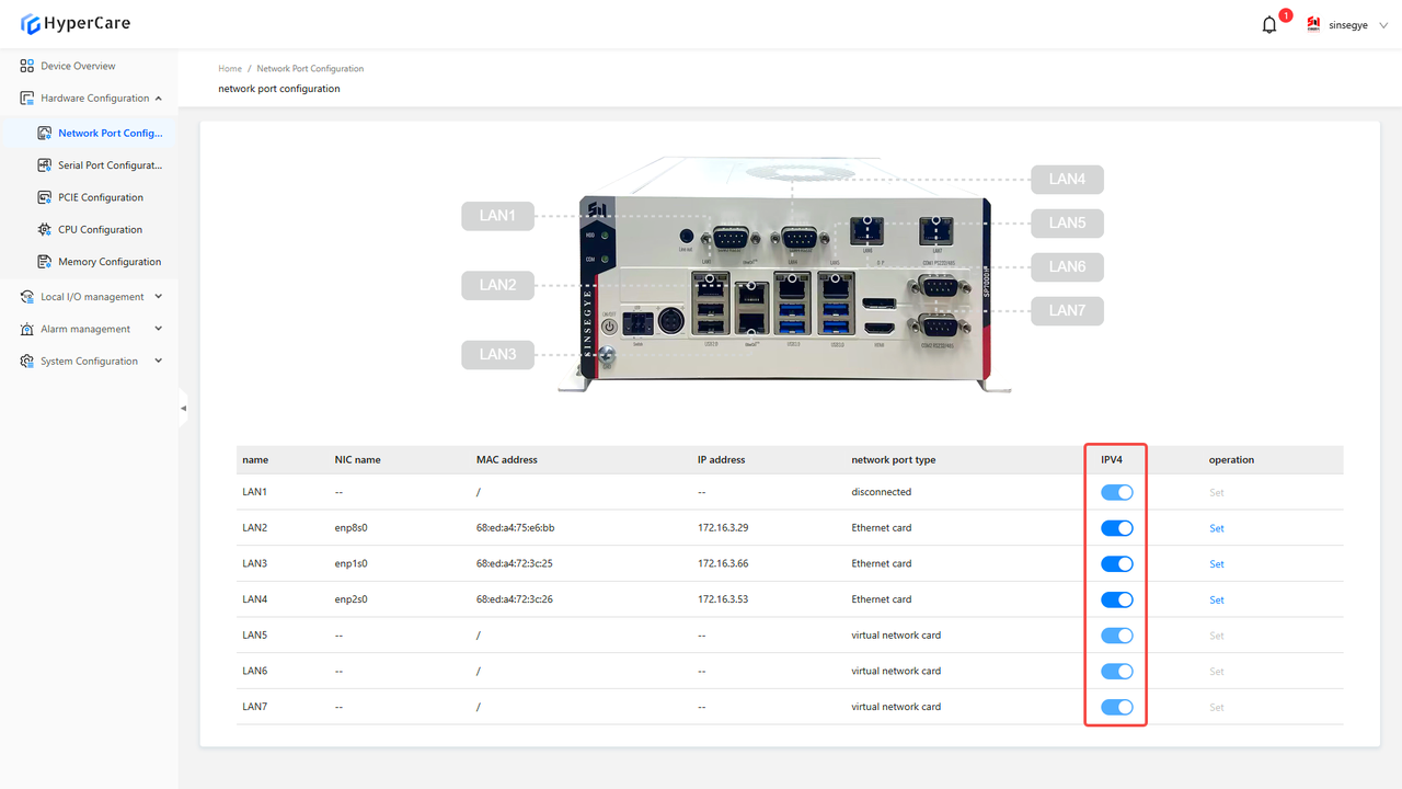
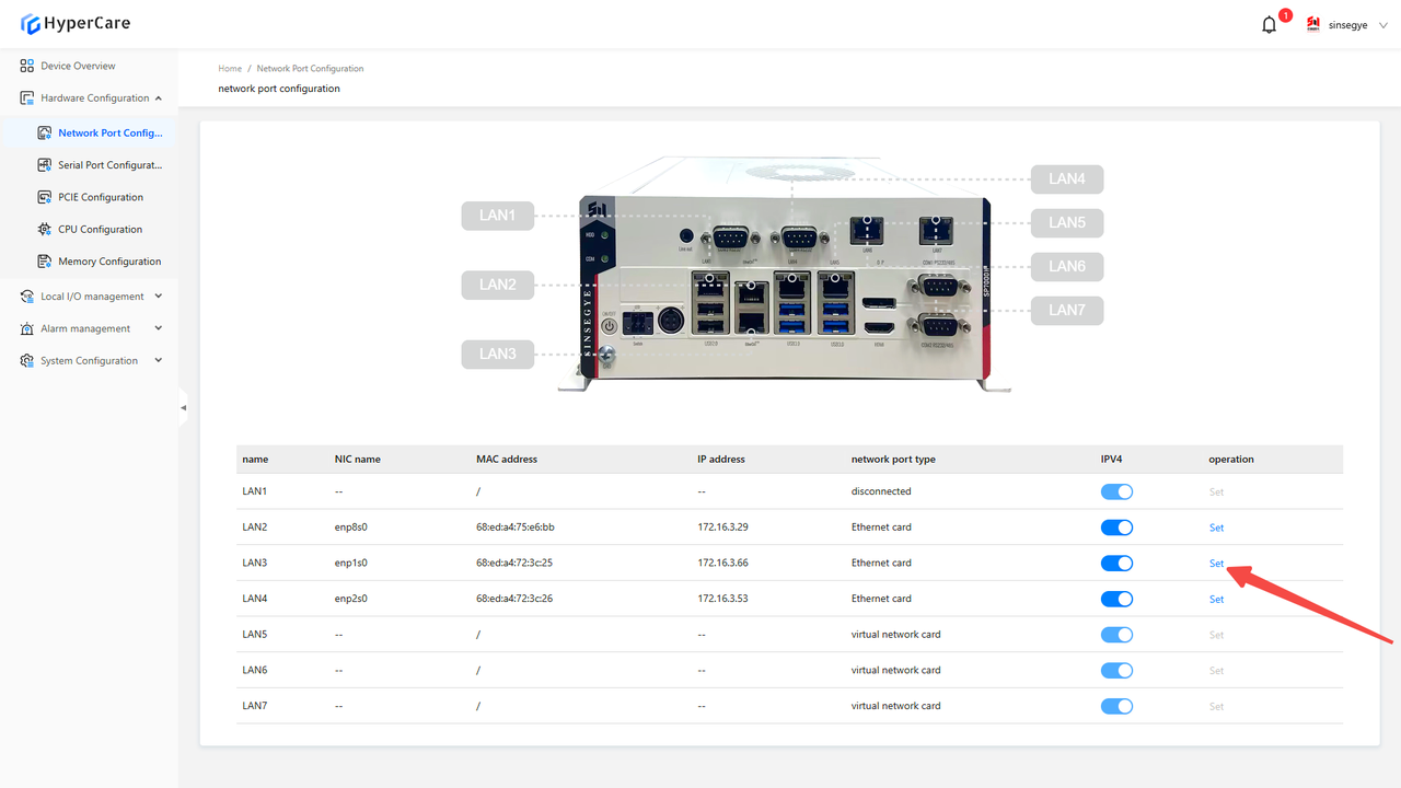
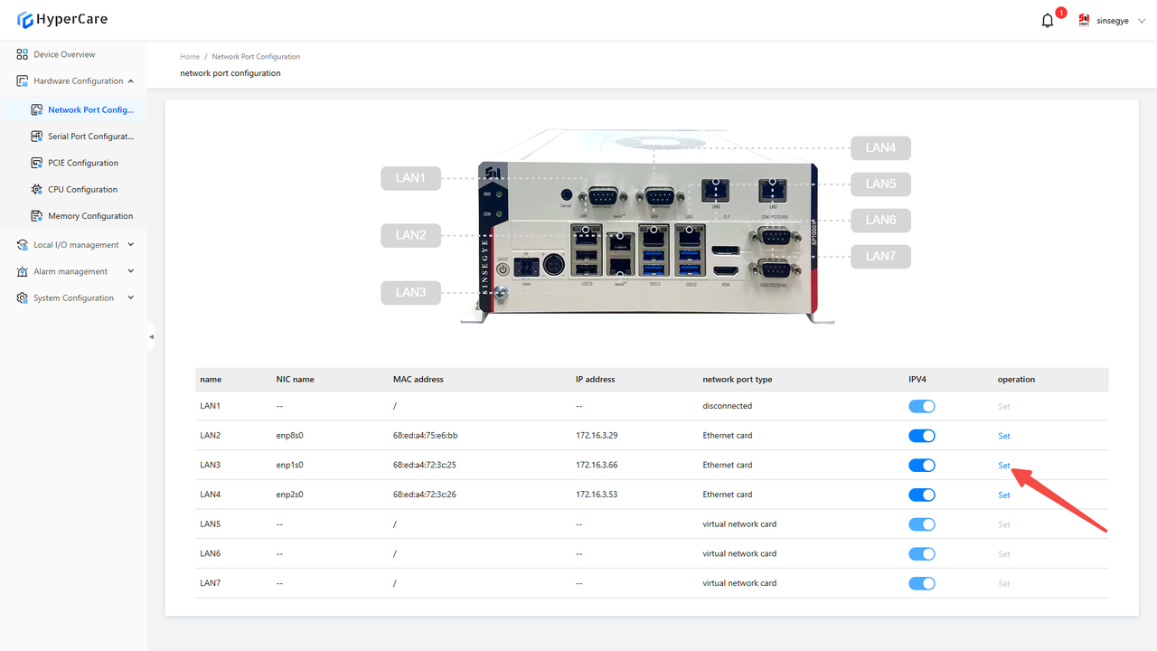
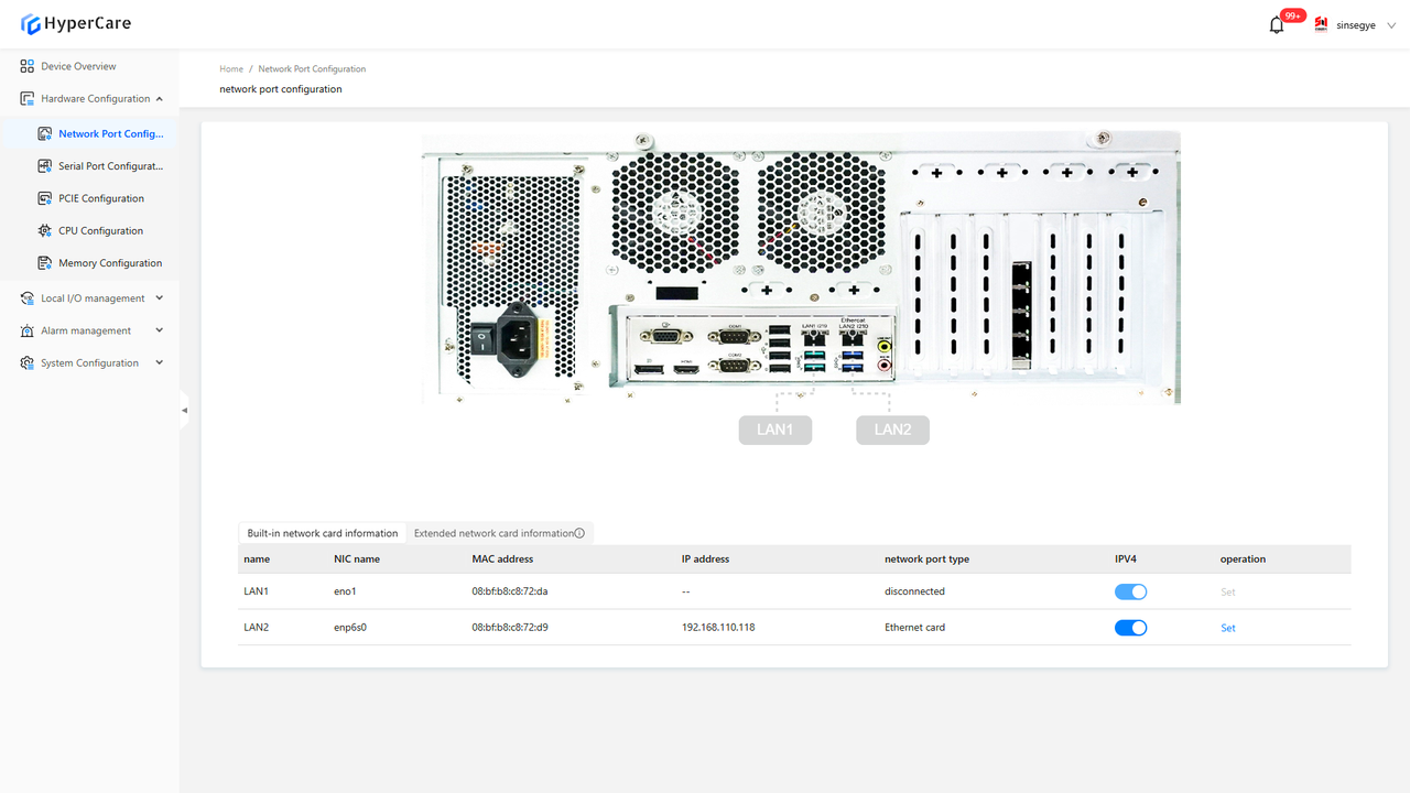
3.3.2 Network port information
View the detailed information such as LAN name, NIC name, MAC address, IP address, and network port type.
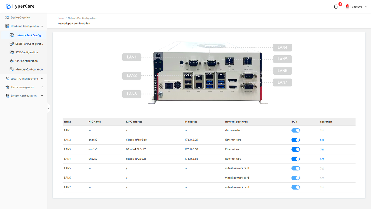
For some models, you can view the extended NIC information
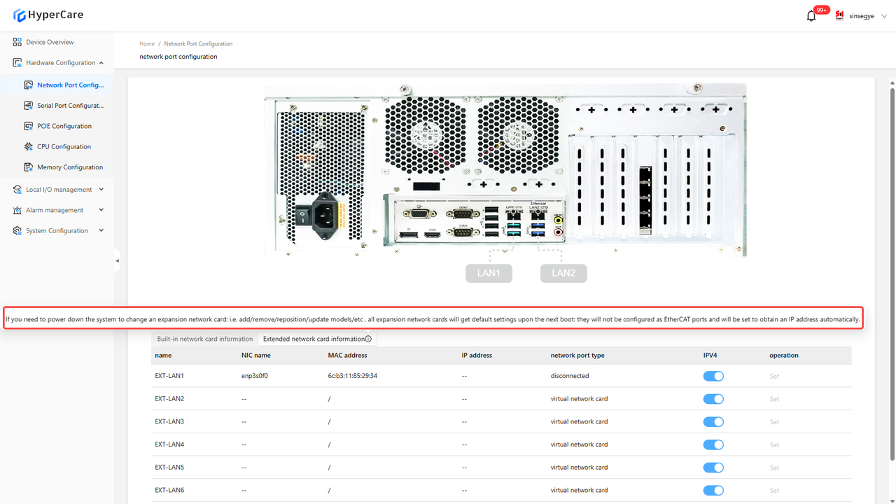
| The extended network card information can be viewed only on SP7022 series, SP5040 series, and SX21 series. |
|---|
3.3.3 EtherCAT Status – Enabled
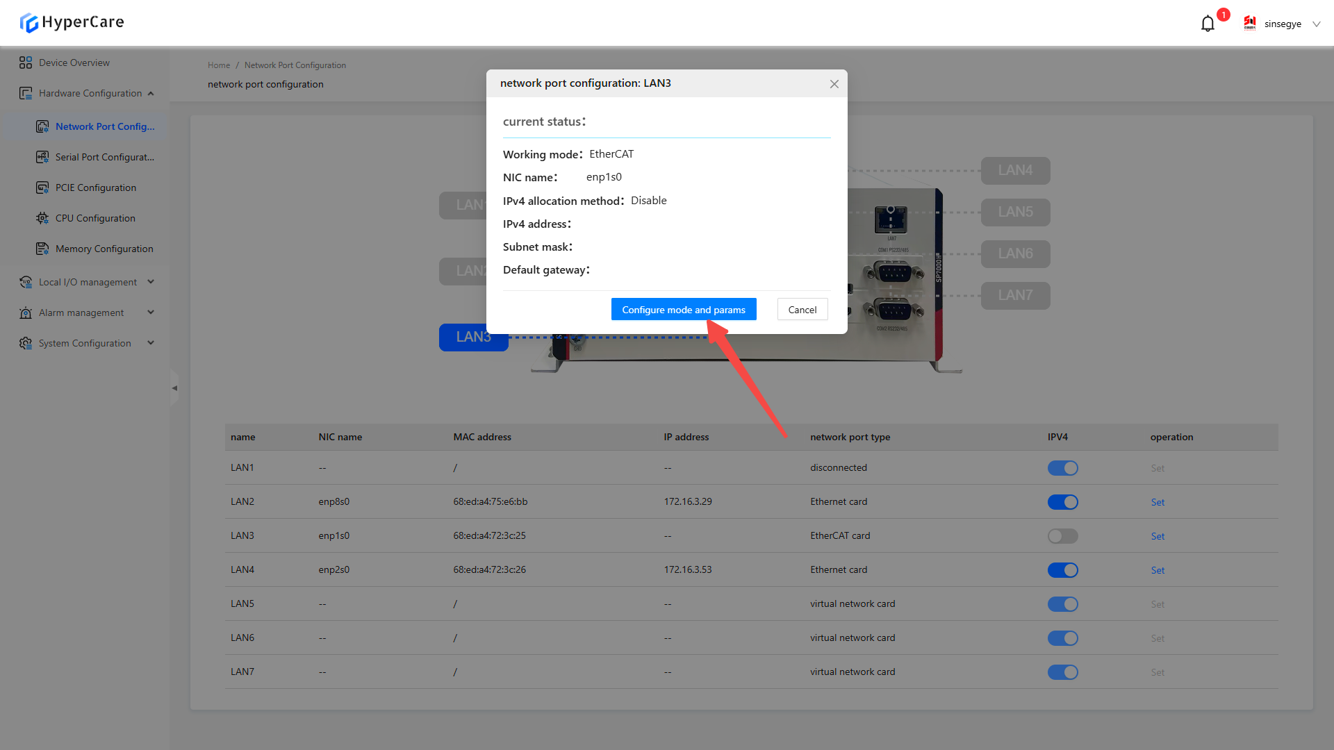
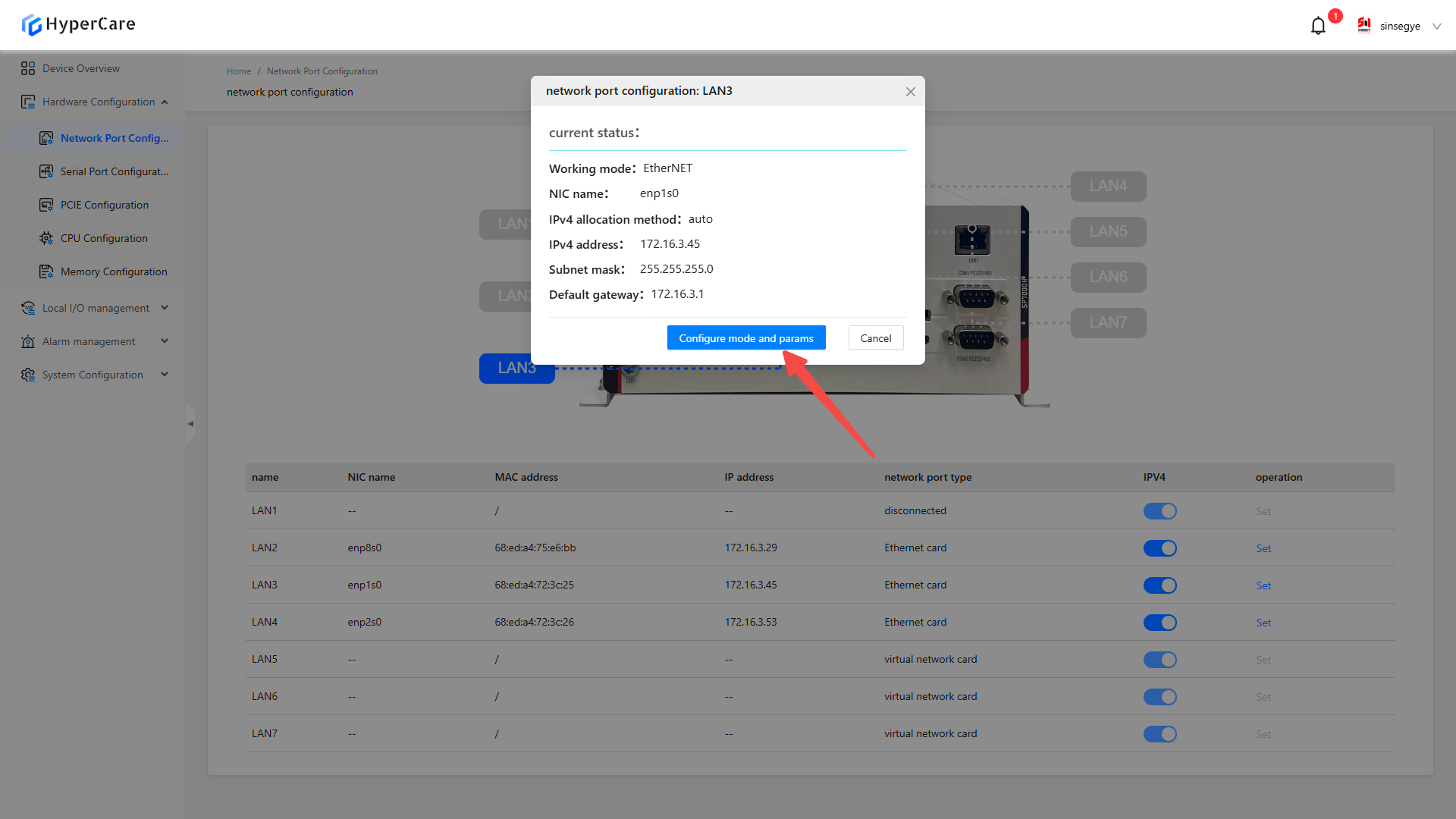
Click the \[Settings] button corresponding to the NIC whose configuration needs to be modified.
Click the \[Configuration Mode and Parameters] button
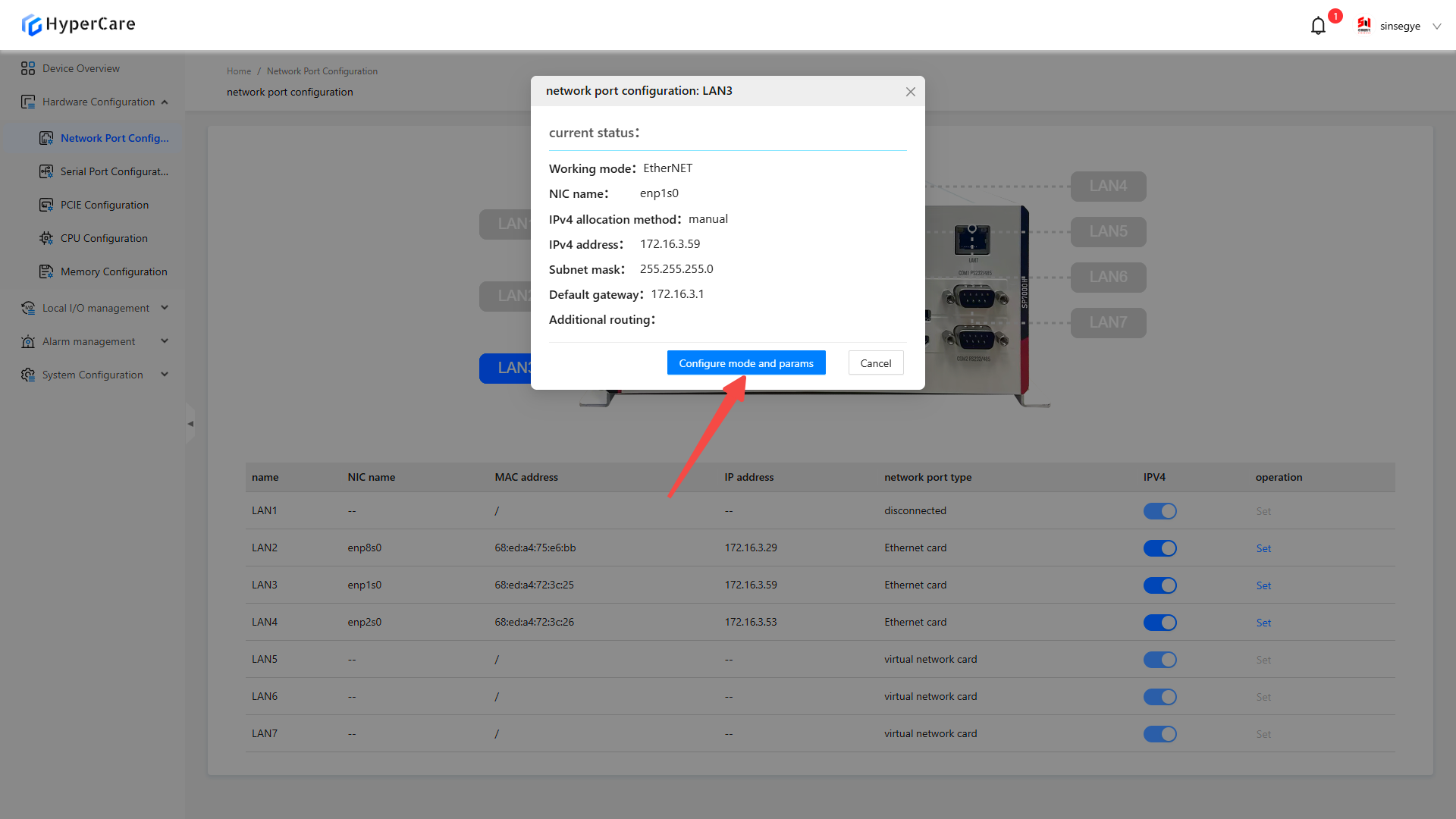
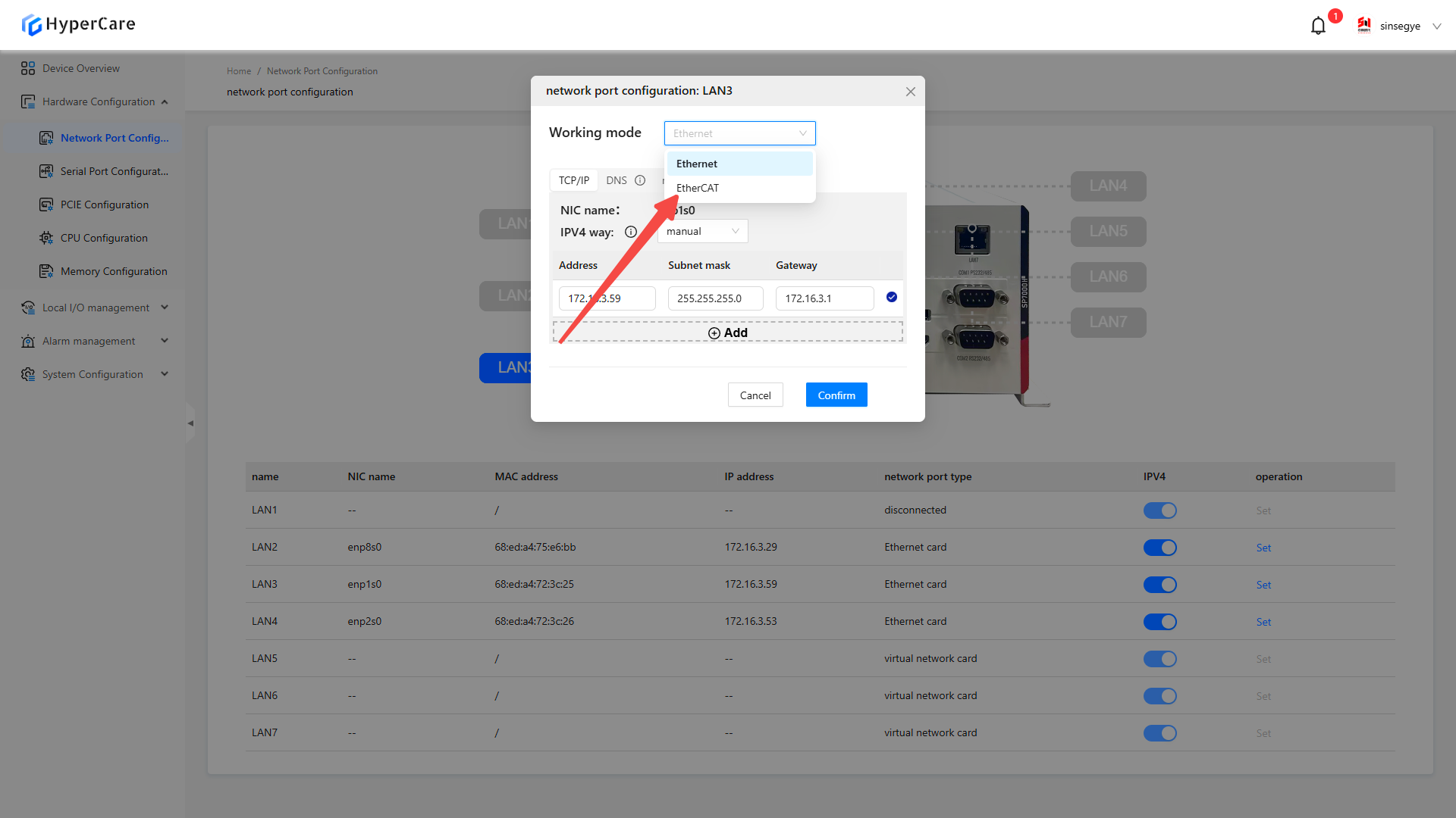
Select \[EtherCAT] as the working mode
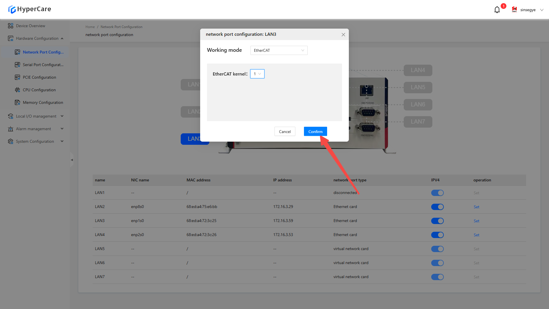
Select the number of cores for the \[EtherCAT kernel].
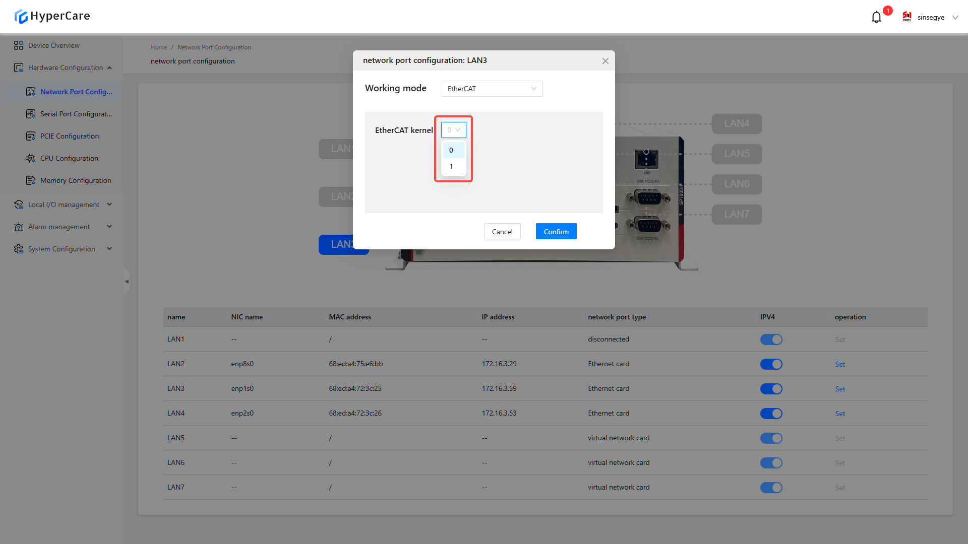
After completing the configuration, click the \[OK] button to make the changes to take effect.
| The LAN1 NIC is the management port and cannot be configured for EtherCAT. |
|---|
3.3.4 EtherCAT Status - Disabled
Click the \[Settings] button for the configured \[EtherCAT NIC].
Click the \[Configuration Mode and Parameters] button.
Select \[Ethernet] as the working mode, with IP set to automatic by default, or to be configured manually.
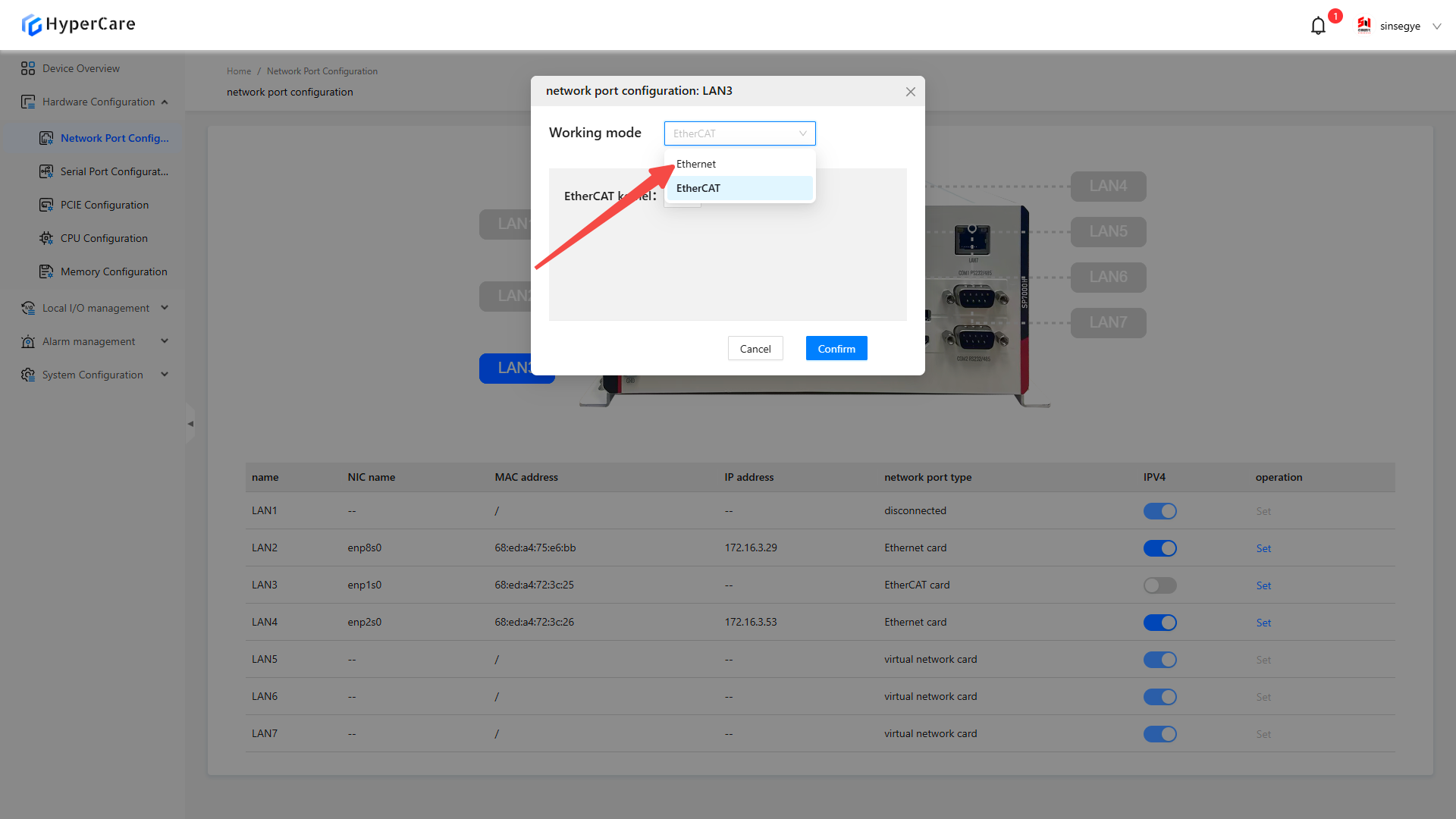
After completing the configuration, click the \[OK] button to make the changes to take effect.
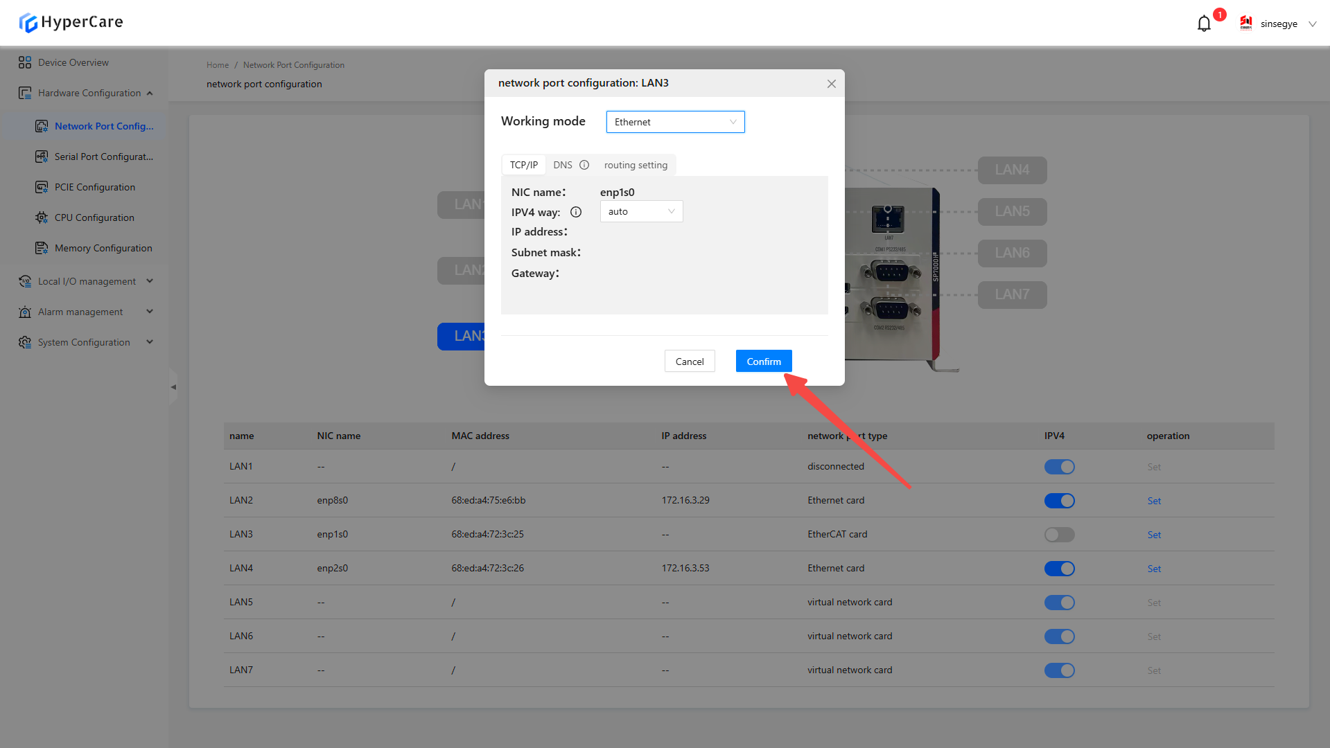
3.3.5 IP Configuration - Automatic
Click the \[Settings] button corresponding to the NIC whose configuration needs to be modified.

Click the \[Configuration Mode and Parameters] button.

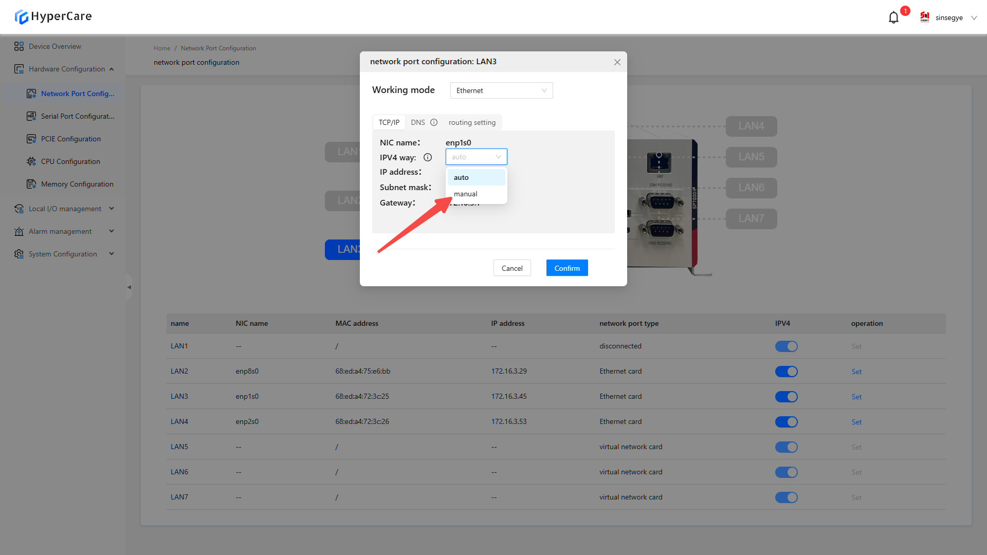
Change the \[IPv4 Mode] to \[Automatic] (default setting).
After completing the configuration, click the \[OK] button to make the changes to take effect.
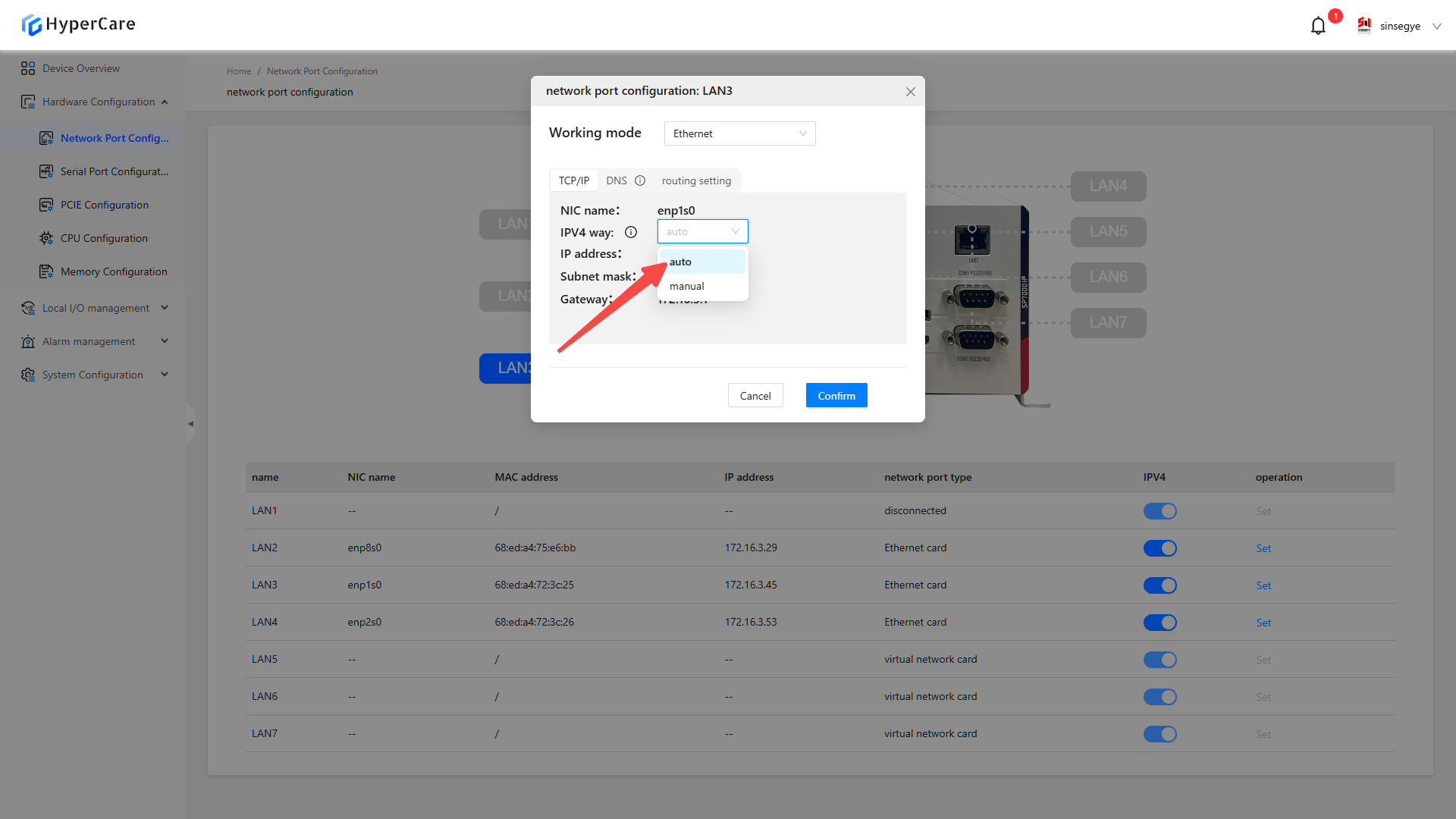
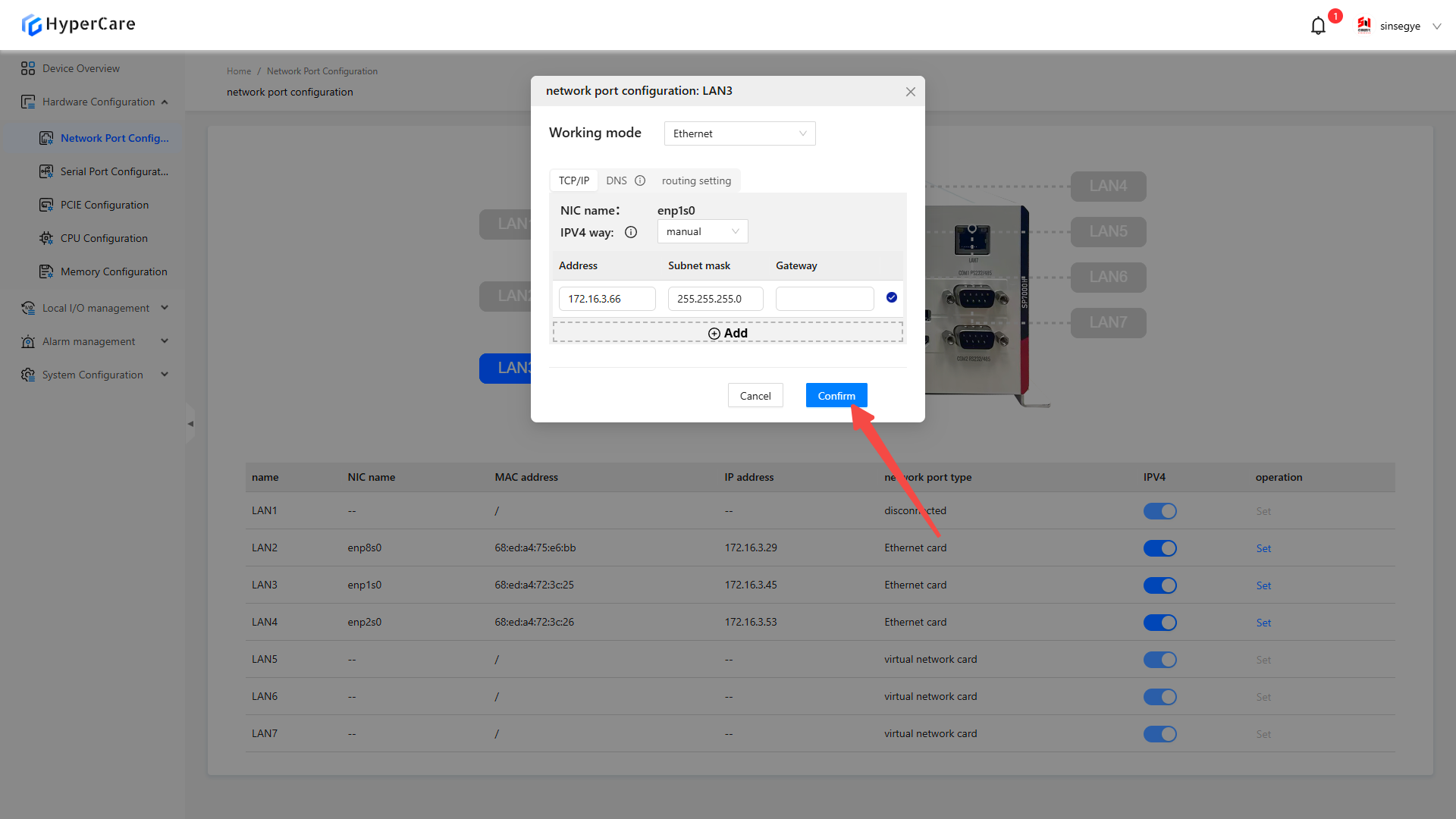
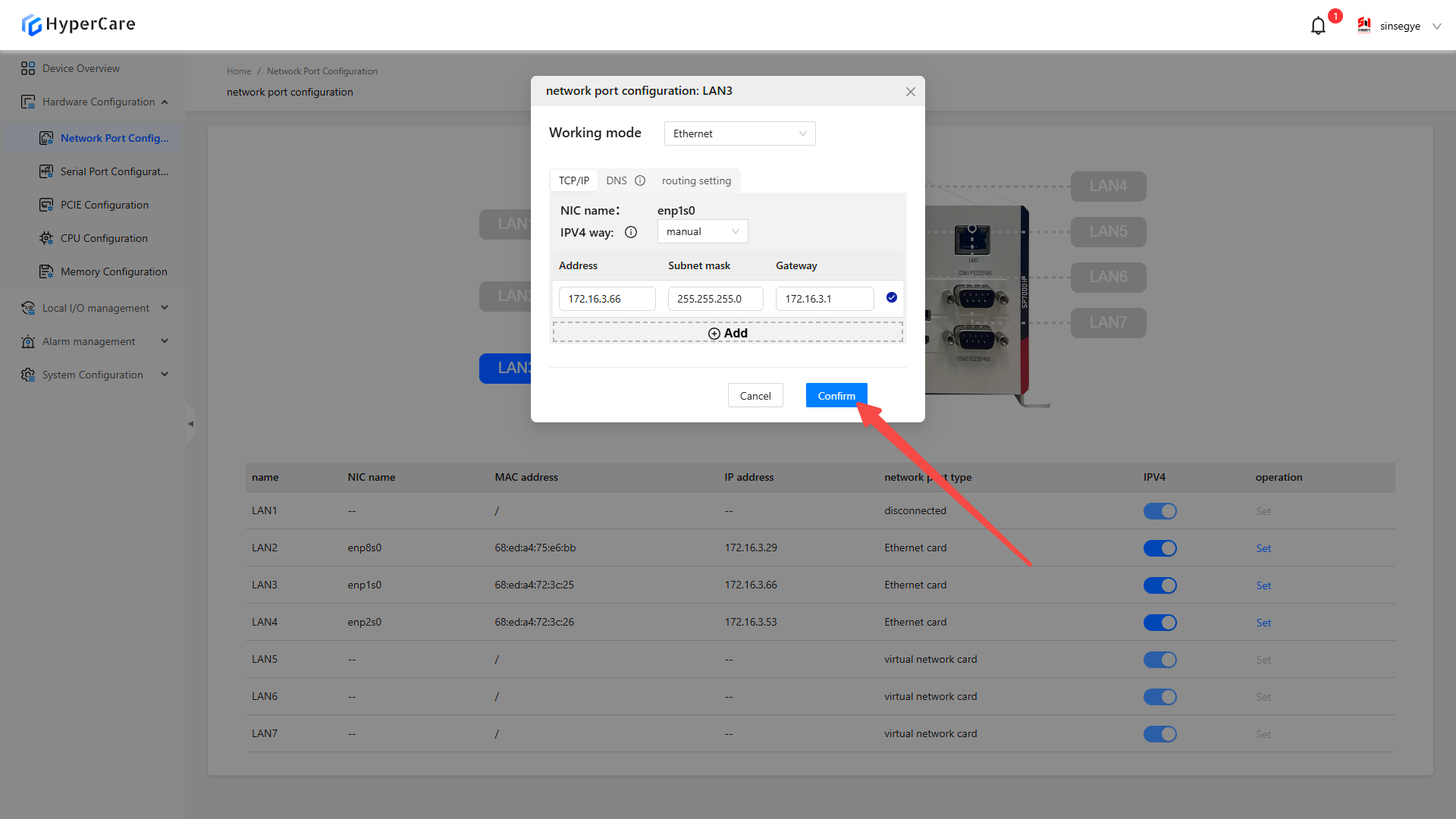
3.3.6 IP Configuration - Manual
Click the \[Settings] button corresponding to the NIC whose configuration needs to be modified.

Click the \[Configuration Mode and Parameters] button.
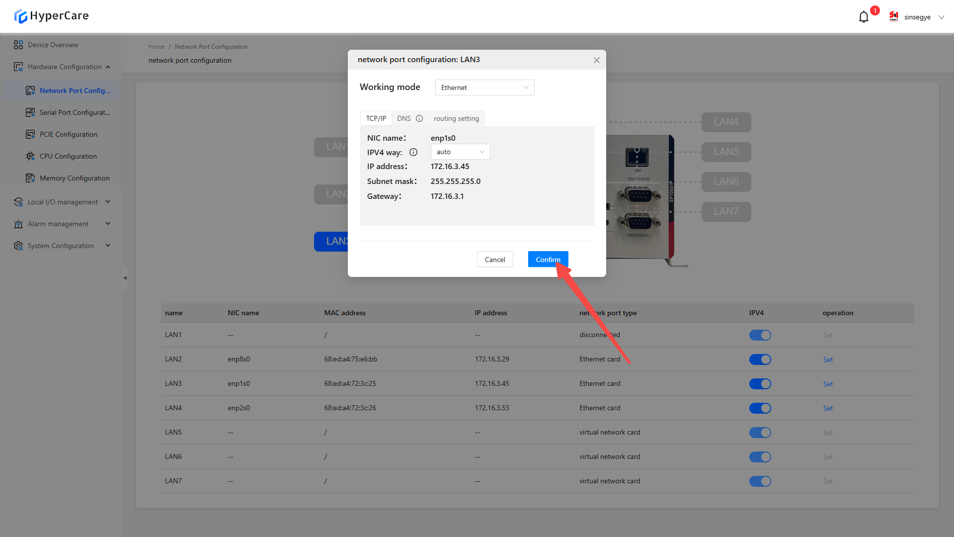
When changing \[IPv4 Mode] to \[Manual], the system will display configuration items for gateway, IP address, and subnet mask.
Set IP address, subnet mask and the gateway according to on-site requirements.
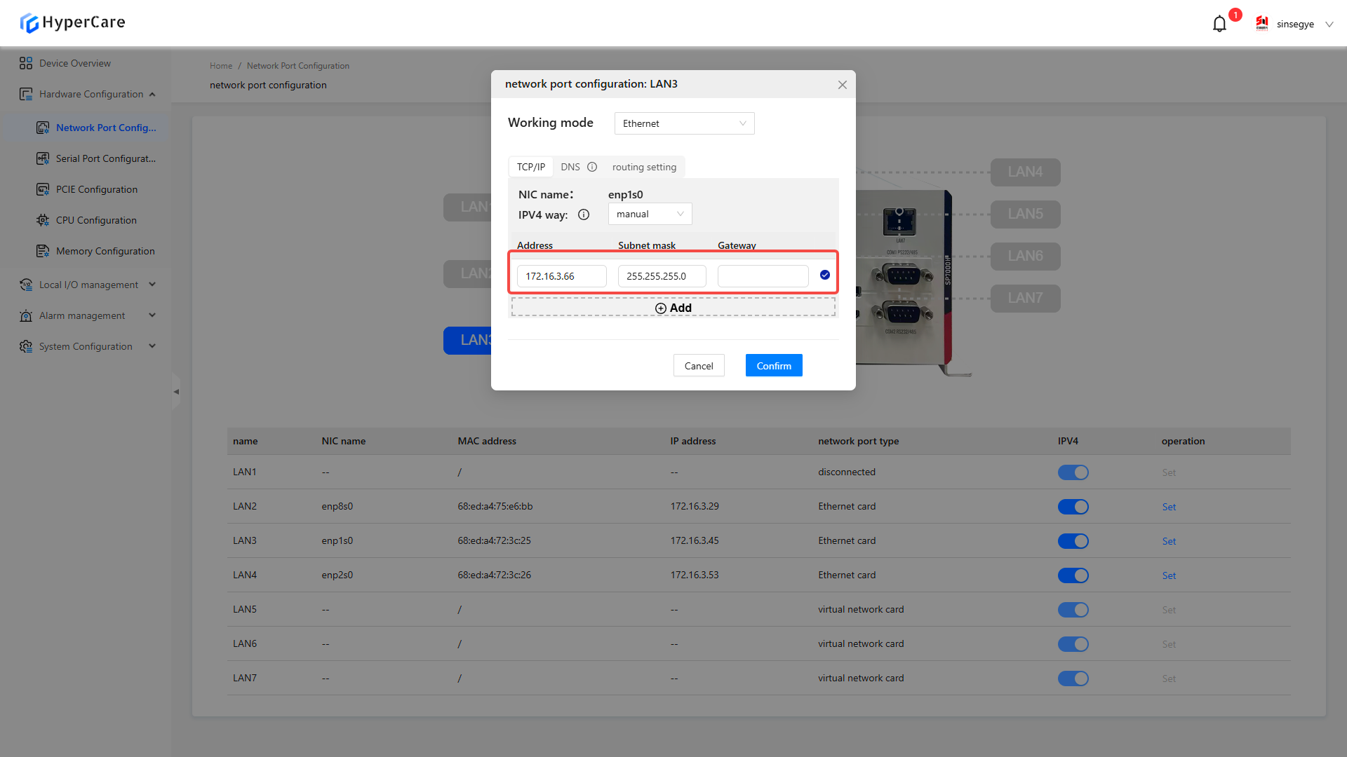
Click the \[⊕ Add] button below to create a new IPV4 entry.
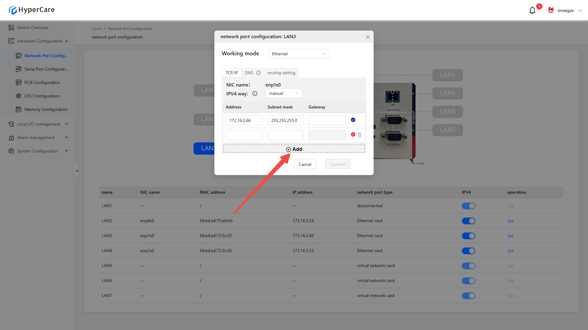
After completing the configuration, click the \[OK] button to make the changes to take effect.
3.3.7 IP Configuration - Disabled
Click the \[Switch] slider corresponding to the NIC that needs configuration modification.
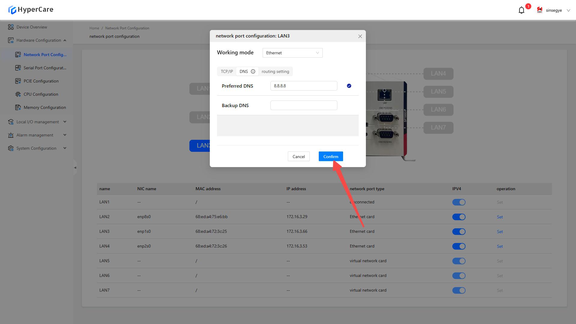
3.3.8 DNS settings
Click the \[Settings] button corresponding to the NIC whose configuration needs to be modified.
Click the \[Configuration Mode and Parameters] button.

Click \[DNS].
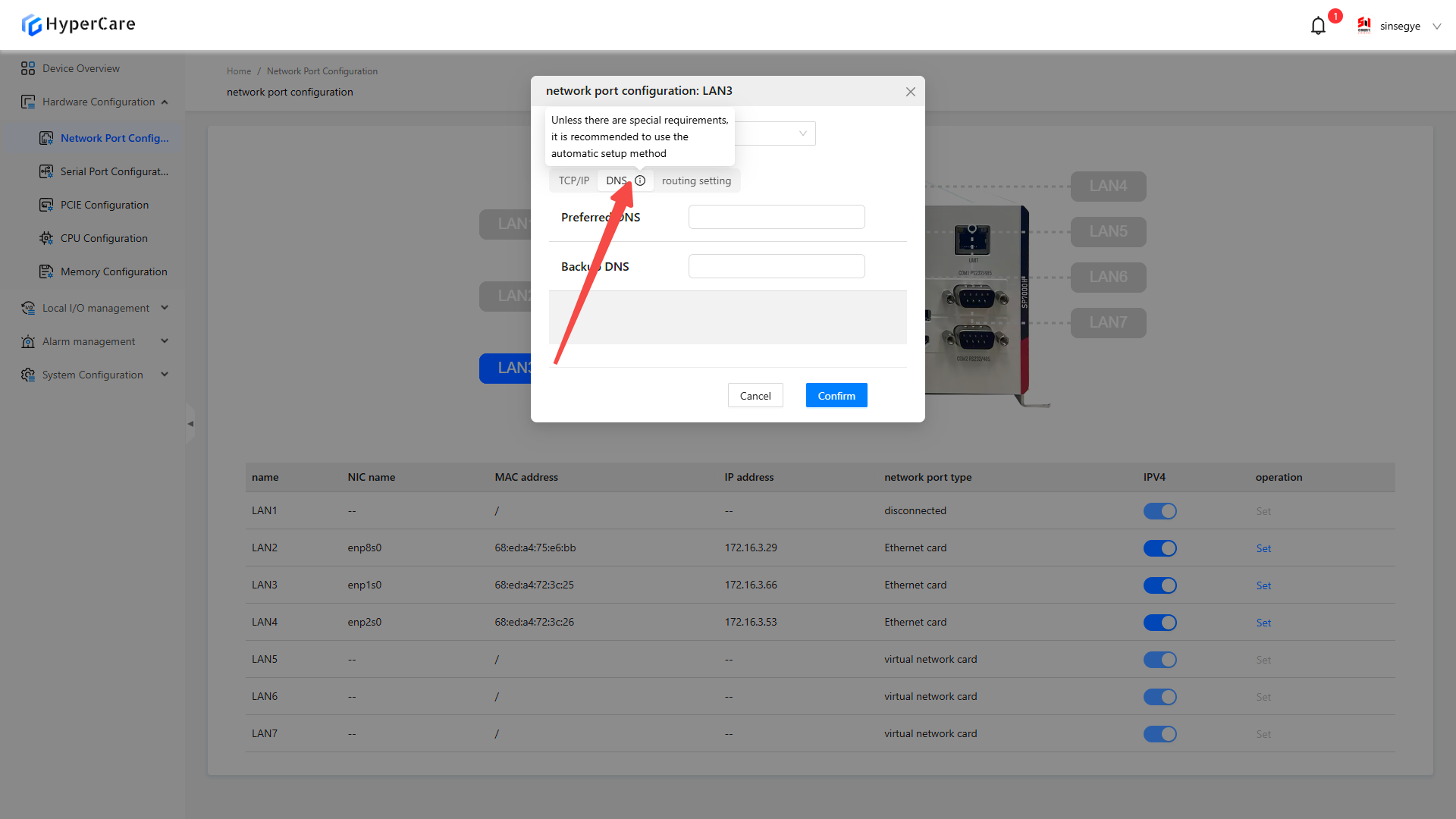
Fill in the corresponding configuration in the text box according to on-site requirements.
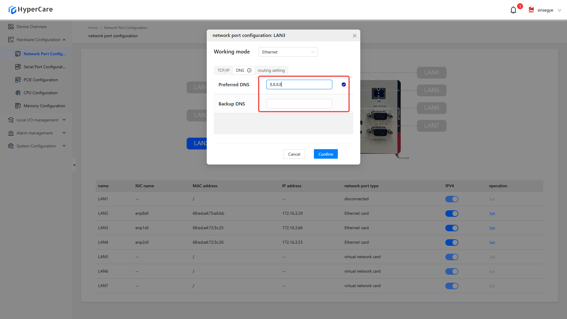
After completing the configuration, click the \[OK] button to make the changes to take effect.
3.3.9 Routing settings
Click the \[Settings] button corresponding to the NIC whose configuration needs to be modified.
Click the \[Configuration Mode and Parameters] button.

Click the \[Routing Settings] button.
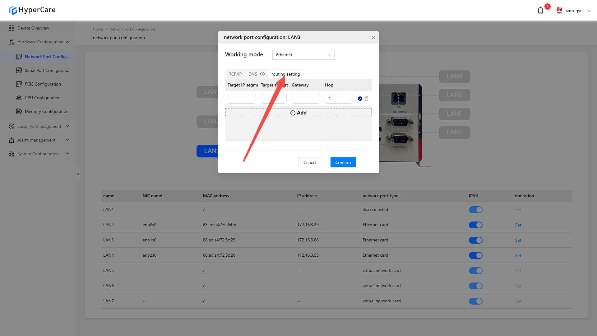
Click the \[⊕ Add] button to create a new routing entry.
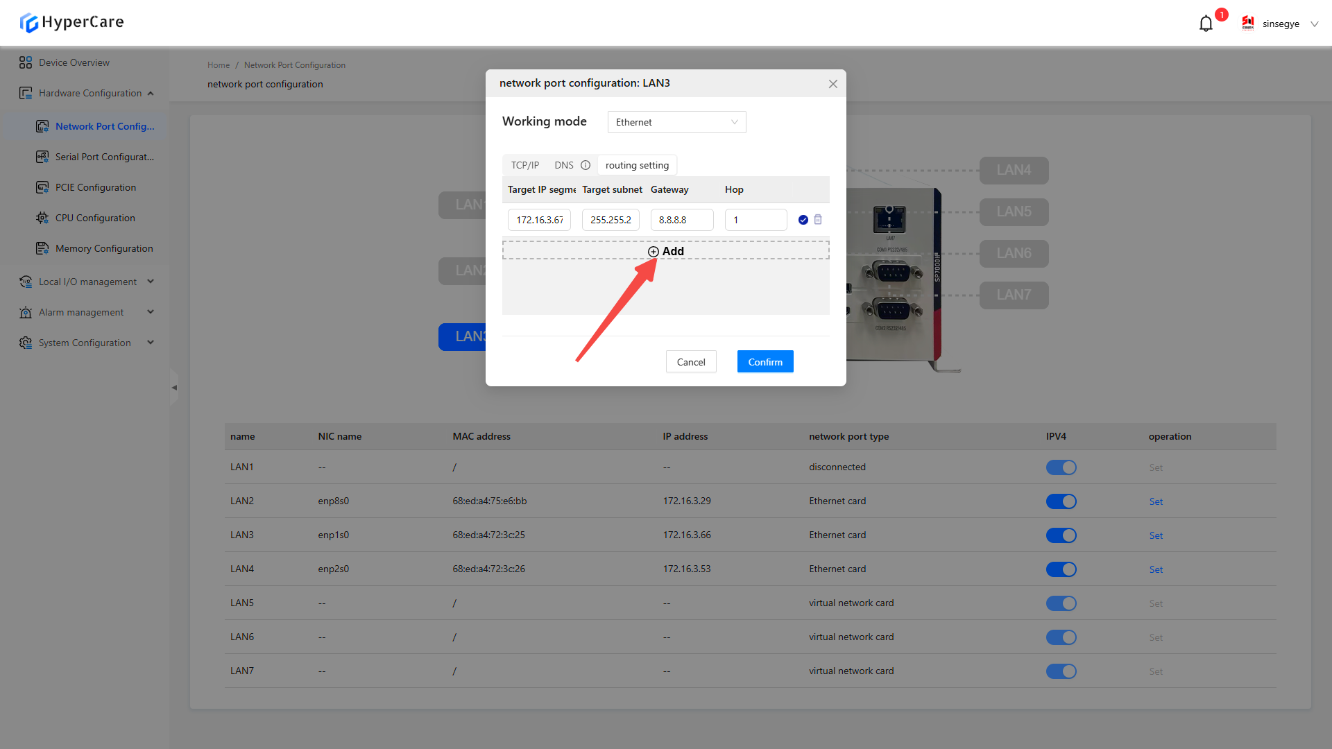
Fill in the configuration items for \[Target IP segment], \[Target Subnet Mask], \[Gateway], and \[Metric] in the text box according to on-site requirements.
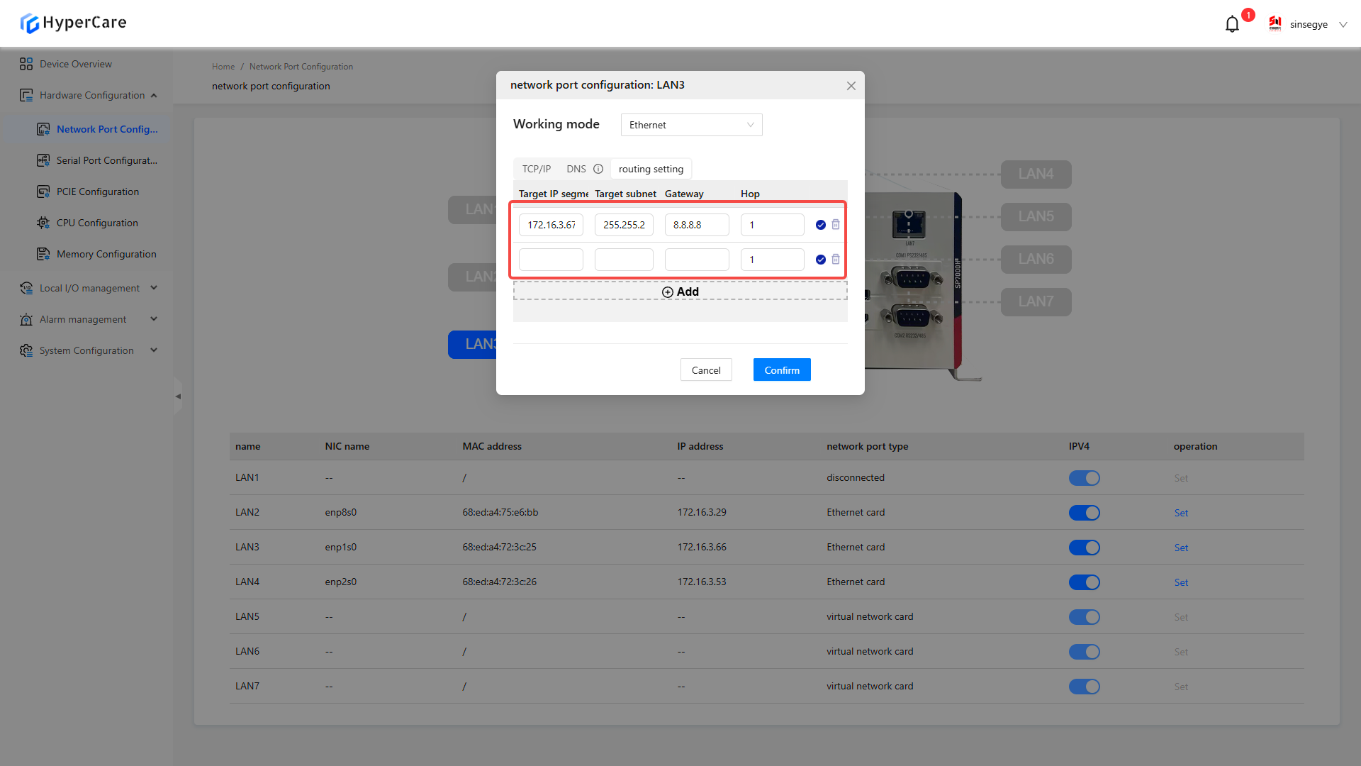
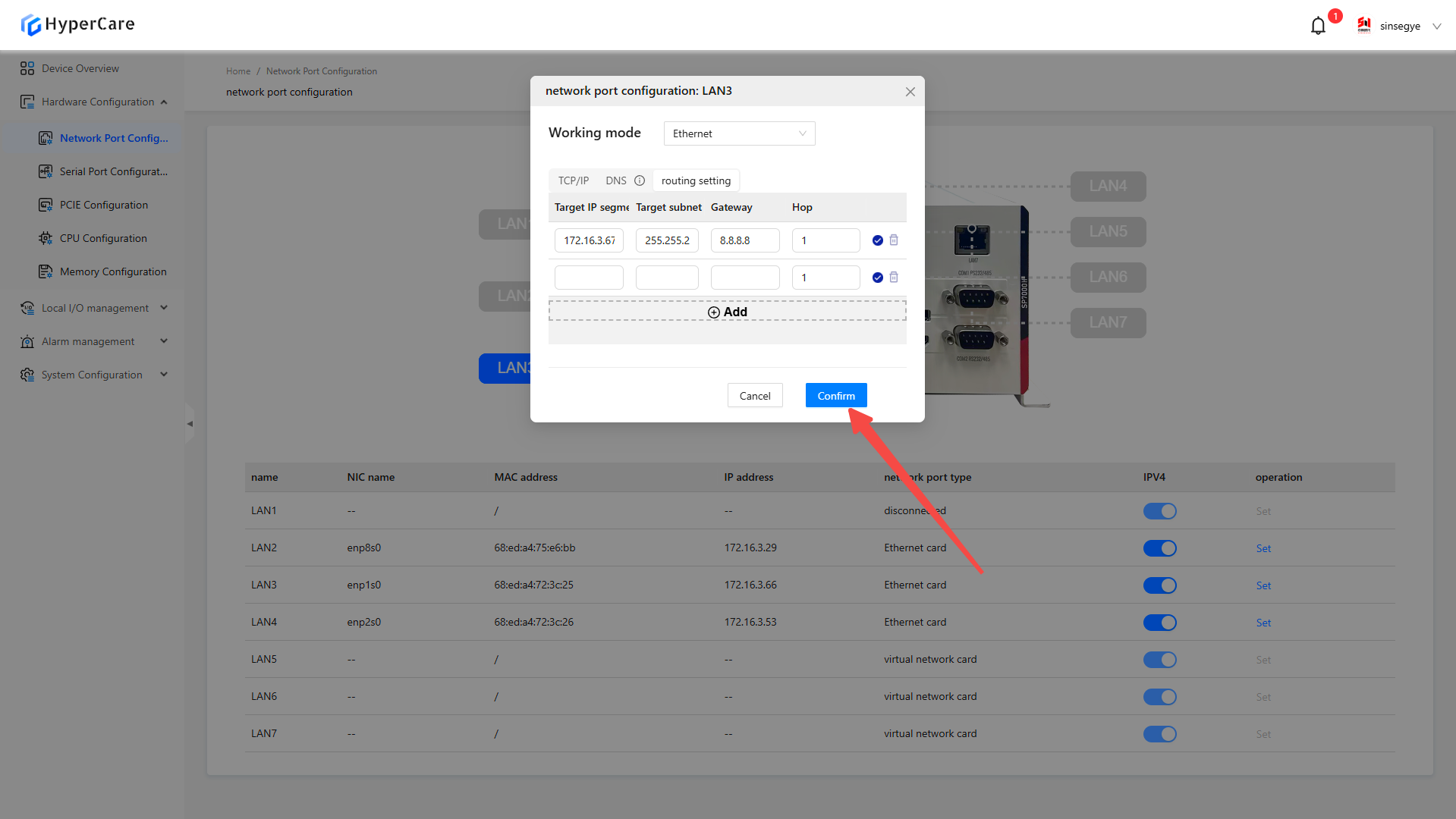
After completing the configuration, click the \[OK] button to make the changes to take effect.
3.3.10 Deletion of configurations
Click the \[Settings] button corresponding to the NIC whose configuration needs to be modified.

Click the \[🗑] icon next to the configured IP or routing entry.
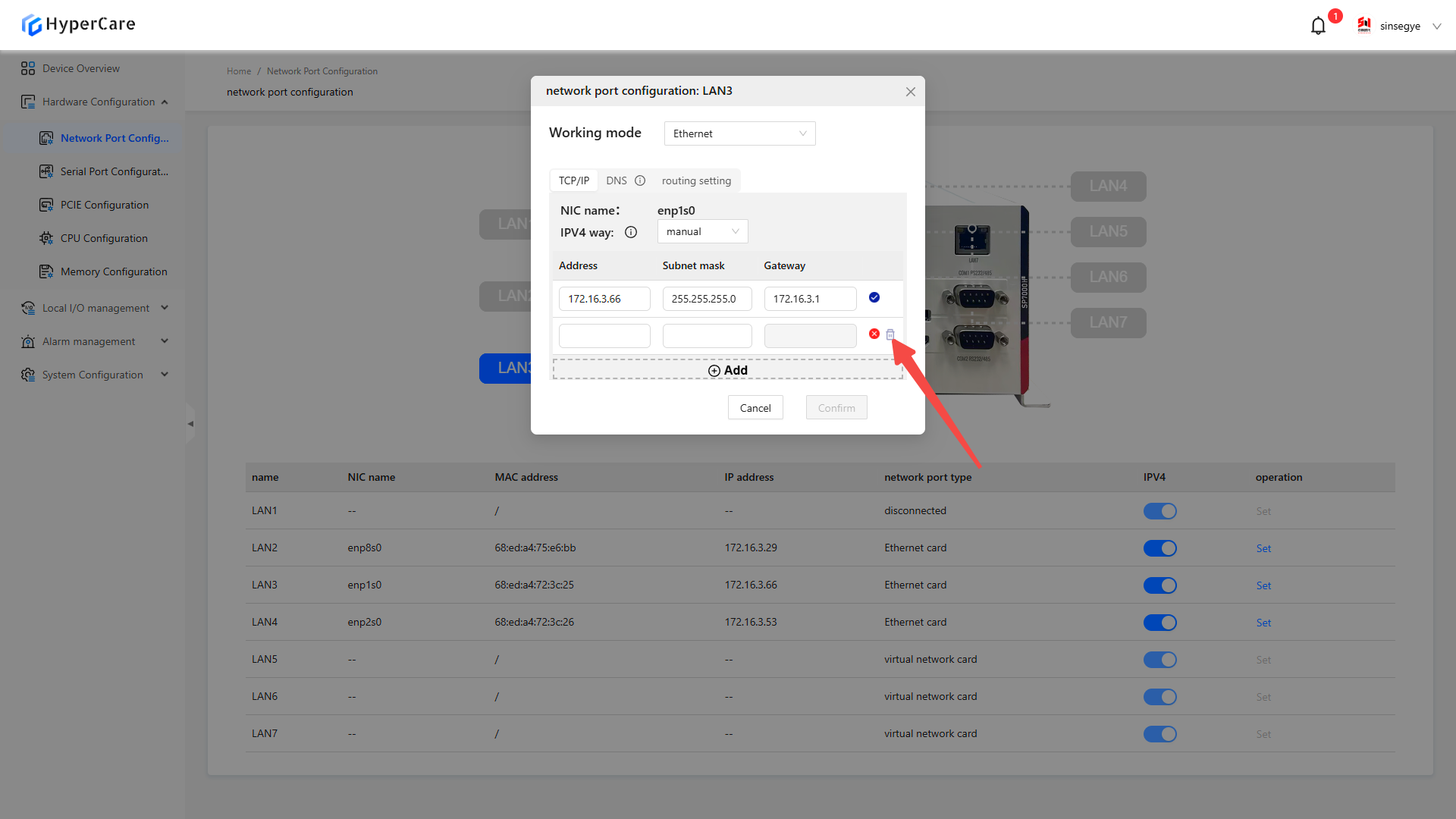
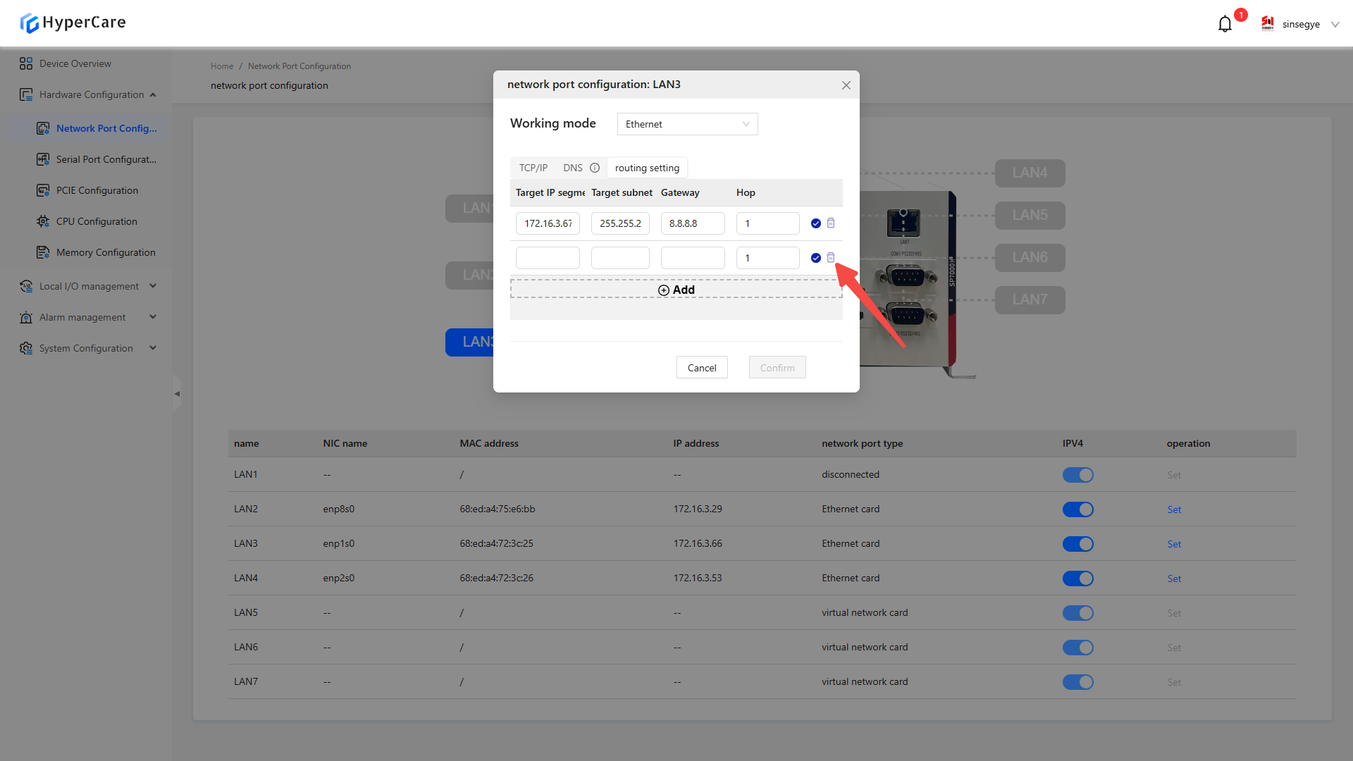
After completing the configuration, click the \[OK] button to make the changes to take effect.
3.3.11 Important notes
-
EtherCAT NIC operates when EtherCAT is enabled.
-
It supports the configurations for built-in NIC and PCIe expansion cards, but does not support expanded USB NIC.
-
For NIC without connected cables, the network port will display as \[Disconnected], and its settings cannot be configured.
-
For NIC to be configured in non-real-time domains, the network port will display as \[Virtual NIC], and its settings cannot be configured.
-
Please perform configuration modifications in a non-production environment.
4. Hardware Configuration - Serial Port Configuration
4.1Scope of Application
| SX58 series | SX51XX-10XX series | SX51XX-11XX series | SX51XX-20XX series | SX52 series | SX2 series |
|---|---|---|---|---|---|
| SX5820-0001 | SX5132-10XX | SX5132-11XX | SX5132-20XX | SX5232-2112 | SX2133 Type I |
| SX5820-0002 | SX5164-10XX | SX5164-11XX | SX5164-20XX | SX2133 Type II | |
| SX5820-0101 | SX5100-10XX | SX5100-11XX | SX5100-20XX | ||
| SX5820-0102 |
4.2 Function Introduction
This function is used to view and modify the serial port mode of the real-time domain.
4.3.Usage Details
4.3.1 Enter the page
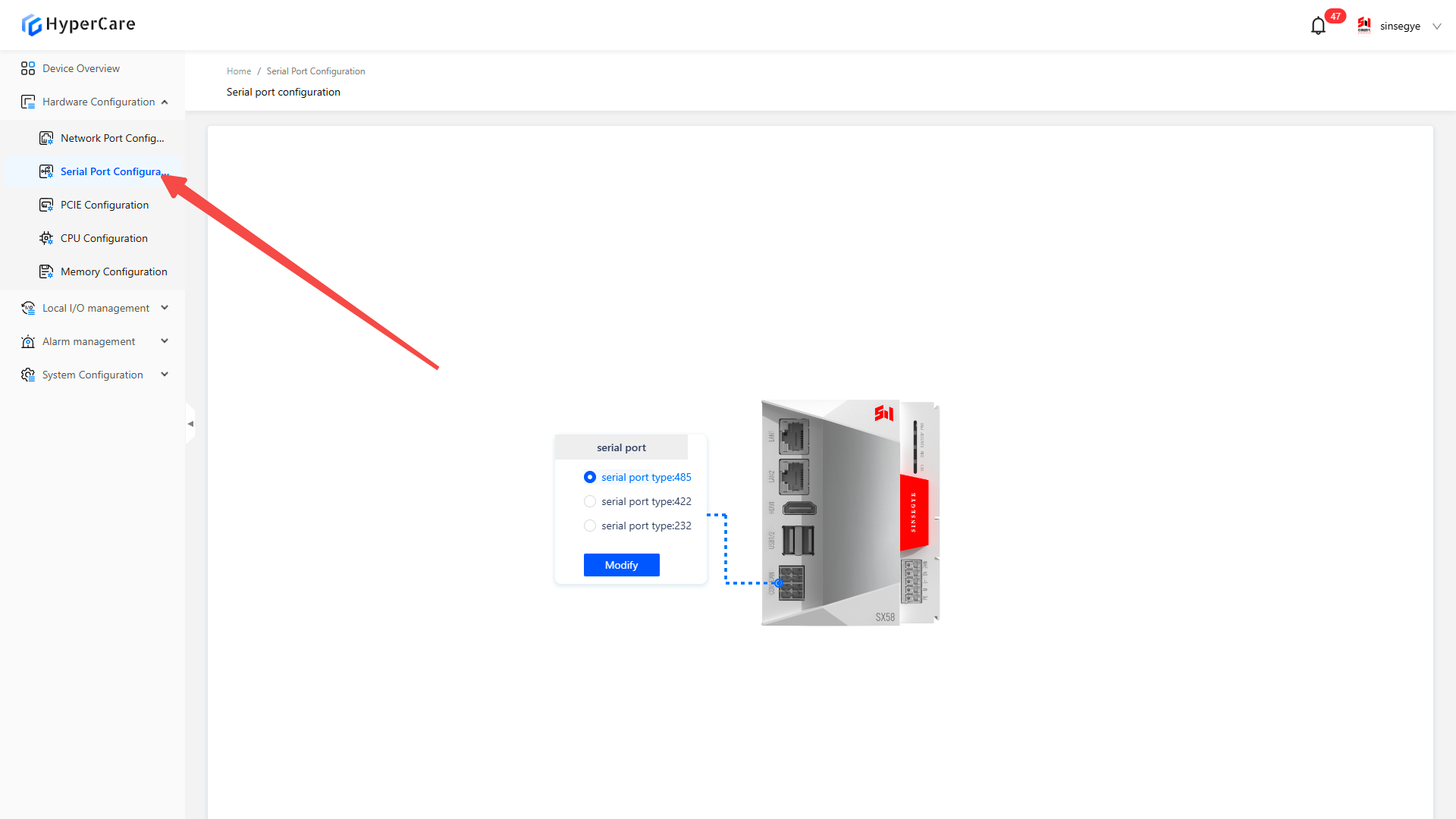
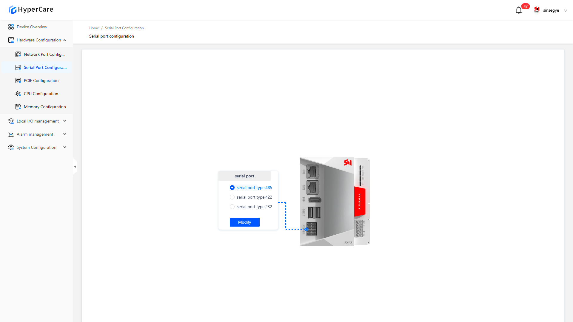
4.3.2 Serial port switching
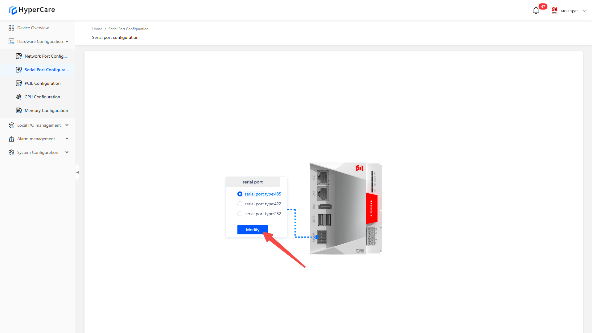
Select the corresponding serial port type \[485/422/232] based on on-site requirements.
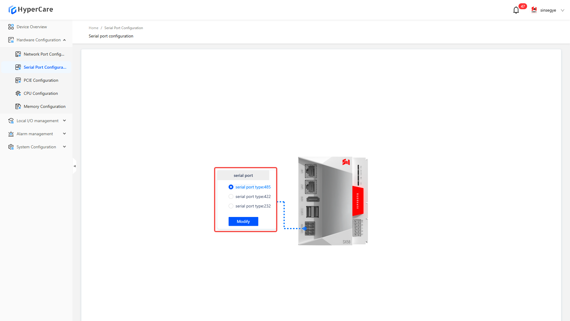
After completing the configuration changes, be sure to click the "Modify" button for the changes to take effect.
4.3.2 Important notes
- Please perform the configuration in a non-production environment.
5. Hardware Configuration - PCIE Settings
5.1 Scope of Application
5.1.1 Built-in PCIE configuration
| SP series | SX2 series | SX5 series |
|---|---|---|
| SP7010-1211 | SX2133 Type II | SX5232-2112 |
| SP7020-2231 | ||
| SP7022-2231 | ||
| SP5040-4331 |
5.1.2 Expanded PCIE configuration
| SP Series | SX2 Series |
|---|---|
| SP7022-2231 | SX2133 Type II |
| SP5040-4331 | |
| SP5040-3331 |
5.2 Function Introduction
This function is used to configure the settings of built-in or extended PCIE device domains.

5.3 Usage Details
5.3.1 Enter the page
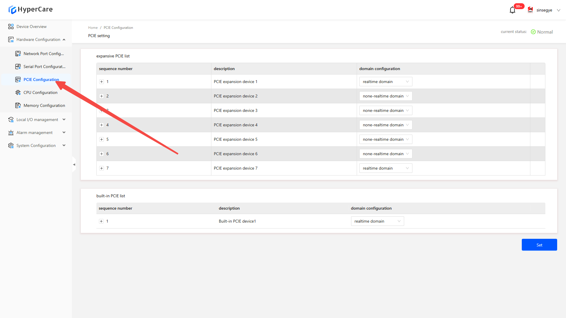
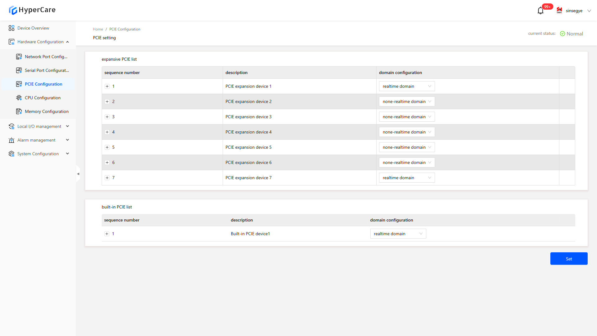
5.3.2 Built-in PCIE
The built-in PCIE list displays the integrated built-in NIC of the iComputer. Users can modify domain configurations and select a corresponding NIC to use in the non-real-time domain (Windows) or real-time domain (Linux).
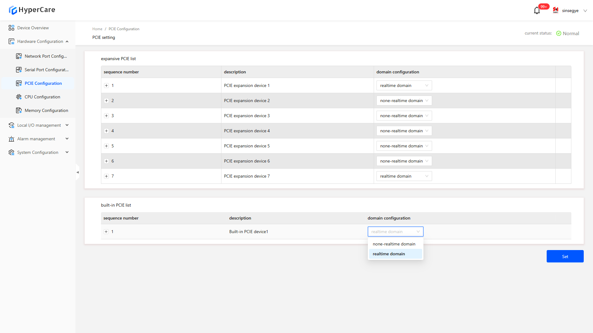
Click the \[+] button in the front of the device number to expand the details.
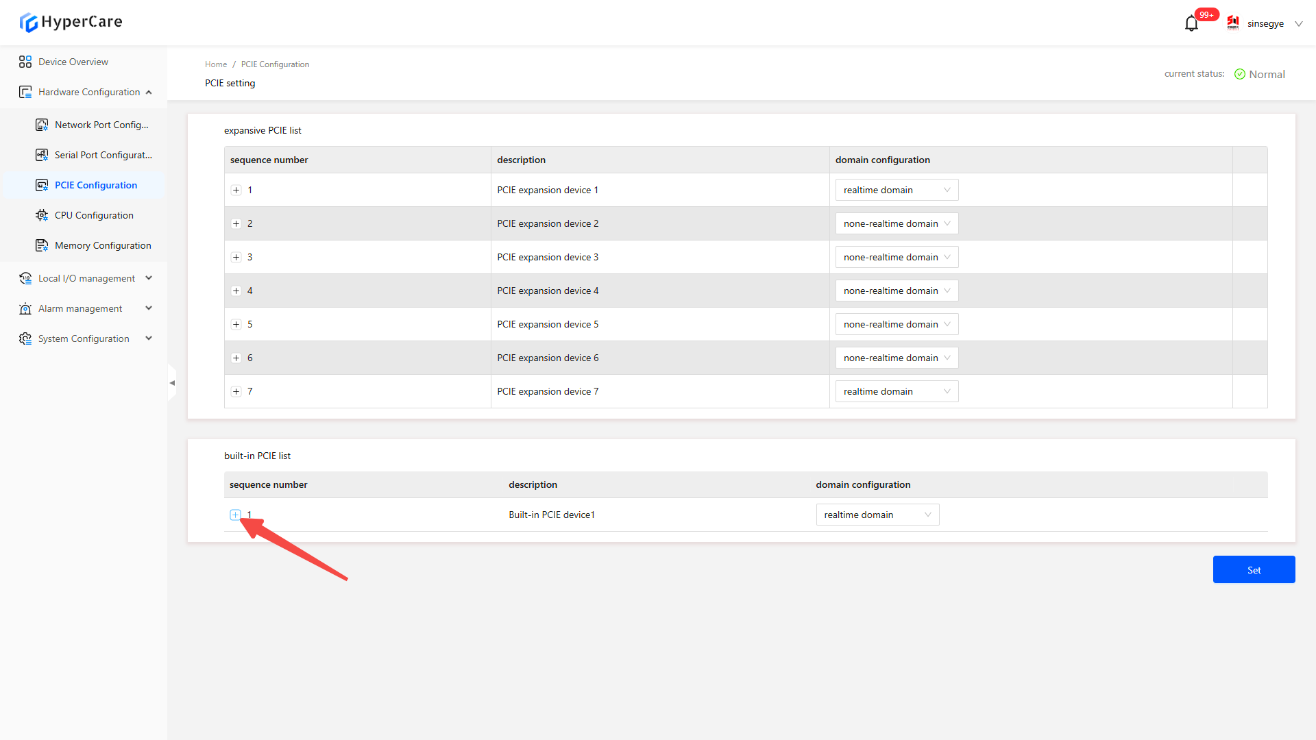
View the the LANx corresponding to the device.
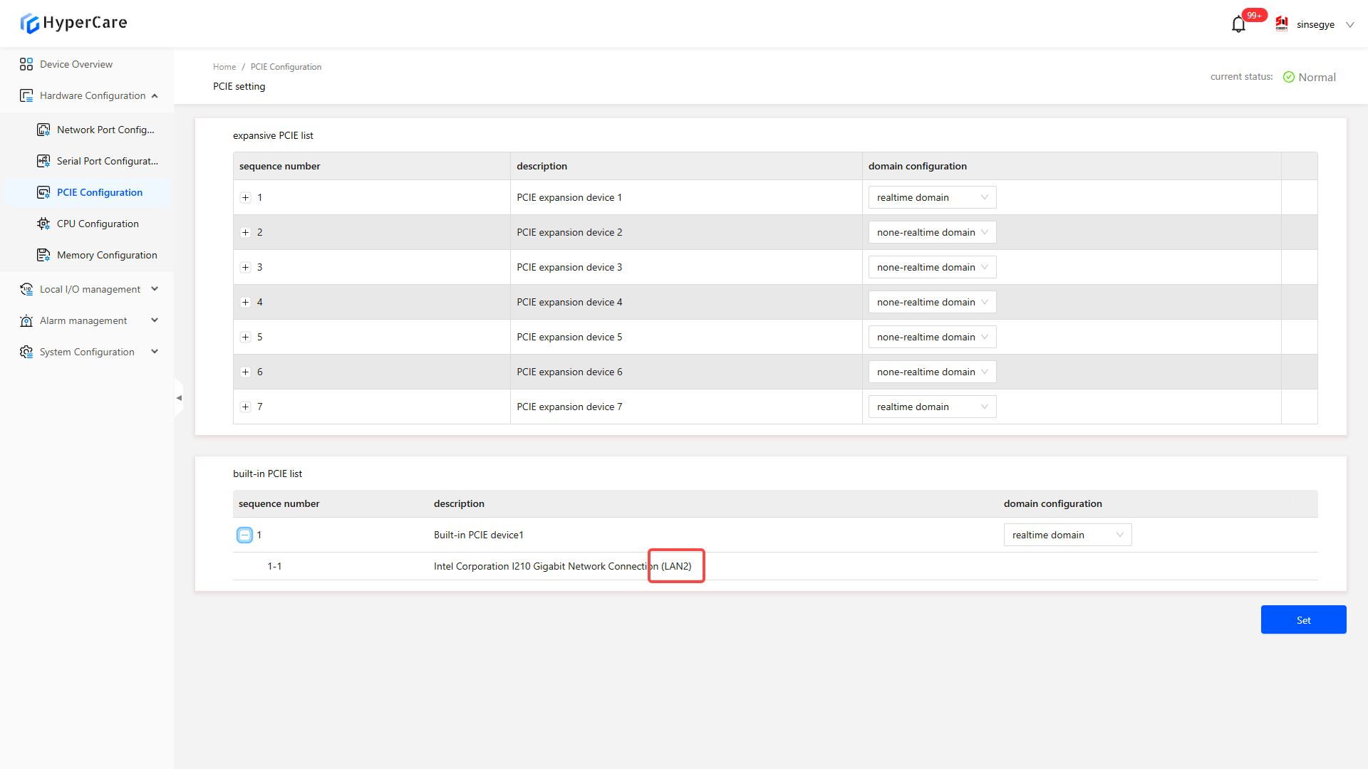
Based on LANx, return to the \[Network Port Configuration] page to view the correspondence in the port information (or directly corresponding to the LANx printed on the physical device).
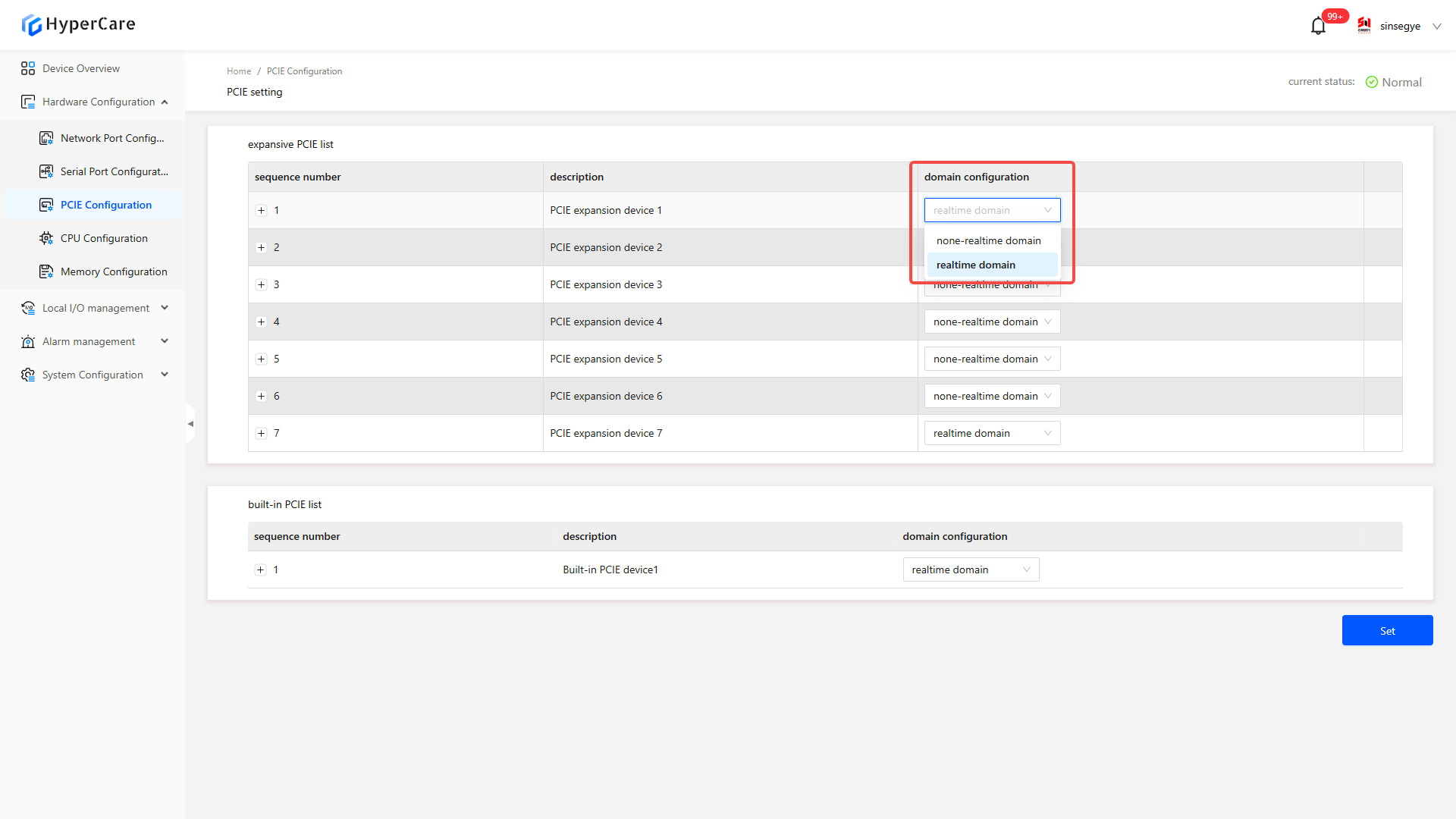
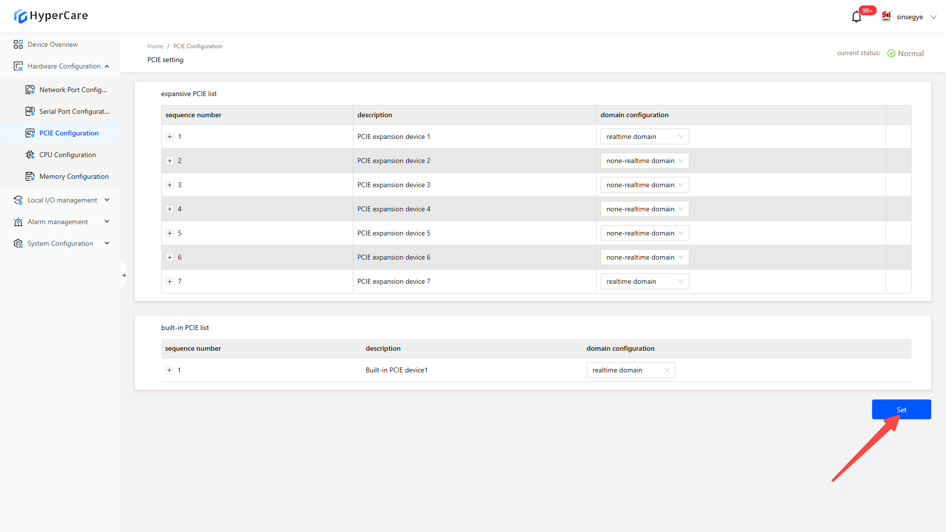
Select the NIC to configure, click the dropdown menu, and modify the domain configuration to \[Real-time Domain] or \[Non-Real-Time Domain].
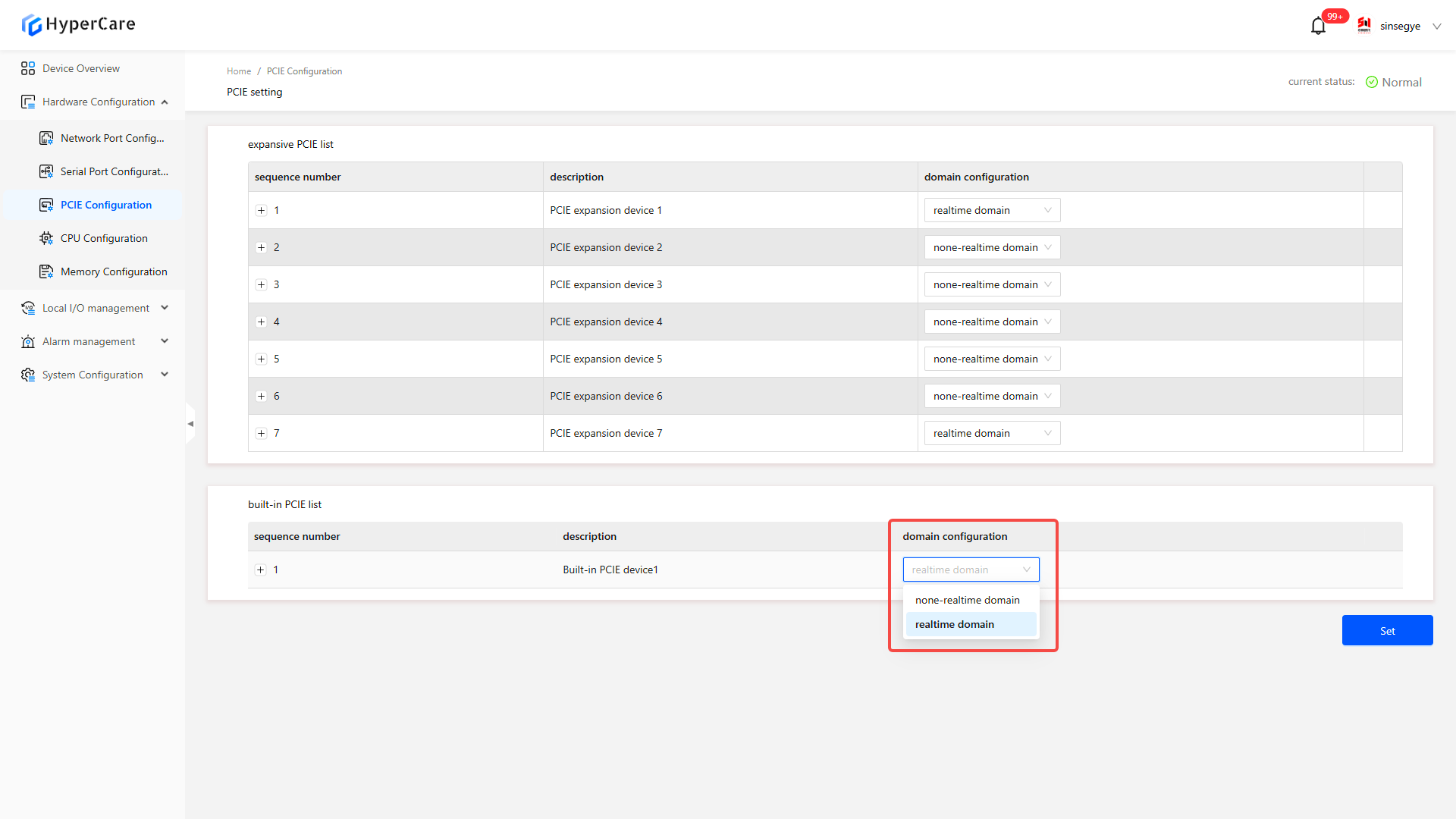
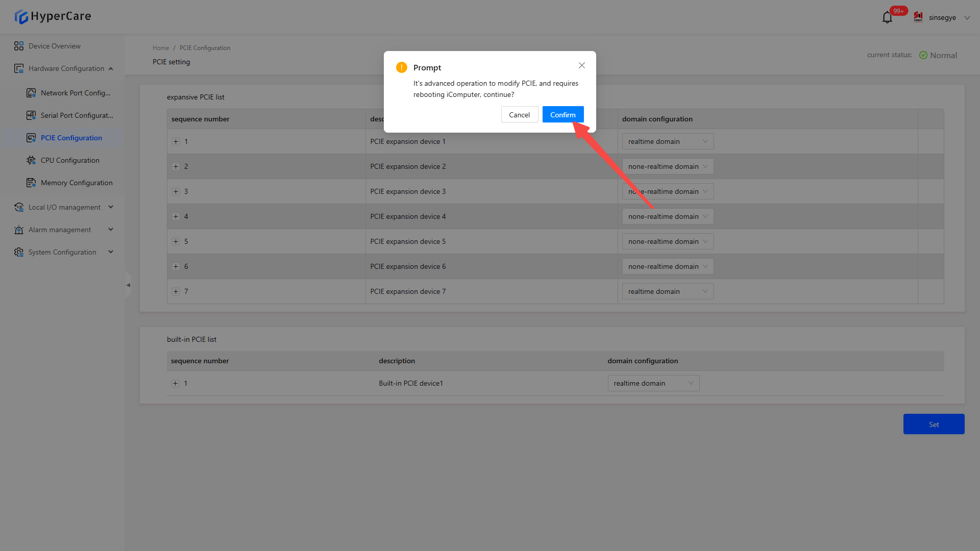
After completing the configuration changes, click the \[Settings] button to display a prompt window.
After clicking \[Confirm], you need to manually restart the device (specific operation method for restart: HyperCare 2.1.4.0 Operation Manual), and at this time, the PCIE status changes to \[Waiting for Power off to Restart].
When the domain is configured as \[Non-Real-Time Domain], the corresponding network port information will show the type as \[Virtual NIC]. This NIC is used for non-real-time domains (Windows). To configure it, relevant operations must be performed in Windows, as the SF8010 webpage no longer supports the configuration.
When configuring the NIC domain settings of EtherCAT, if you modify it to a non-real-time domain and then change it back to a real-time domain, the NIC will enter the \[Disabled] state. To use this NIC again, you need to reset it in the network port configuration.
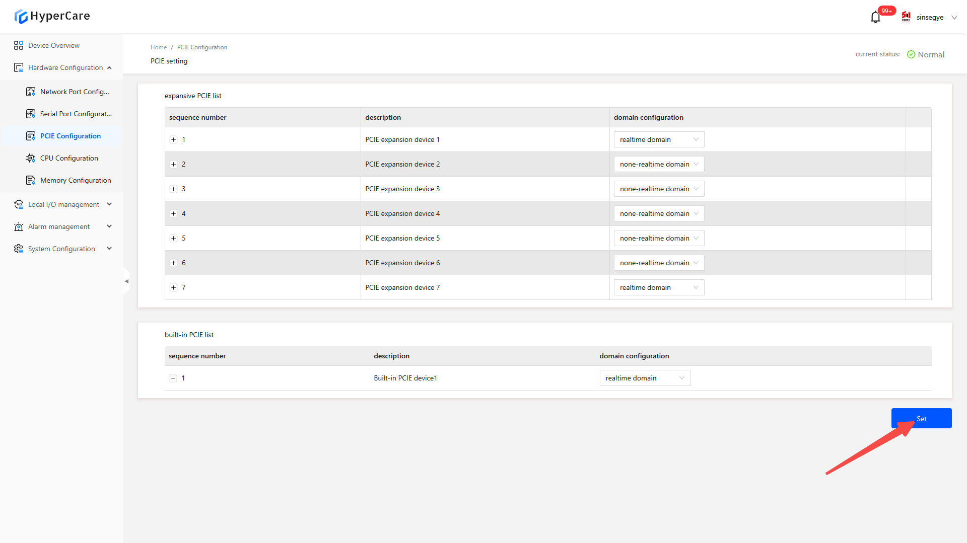
5.3.3 Expanded PCI
| SX2133 Type II has verified expandable modules: four-port Ethernet module, serial/CAN module, and decoding module (for multiple expansion connections, and the decoding module shall be placed last). SP7022-2231 has verified expandable modules: P1000 graphics card, RTX 3060 graphics card, 2-port 422/485 serial port card, 4-port NIC, 6-port NIC, GT 730 graphics card, and PCIe-9110I CAN card.SP5040-3331 has verified expandable modules: P1000 graphics card, RTX 3060 graphics card, RTX 3080 graphics card, RTX 4060 graphics card, 4-port NIC, 6-port NIC, GT 730 graphics card, PCI network port card, and PCI serial port card.SP5040-4331 has verified expandable modules: P1000 graphics card, RTX 3060 graphics card, RTX 3080 graphics card, RTX 4060 graphics card, 2-port 422/485 serial port card, 4-port NIC, 6-port NIC, GT 730 graphics card, PCIe-9110I CAN card, PCI CAN card, PCI network port card, and PCI serial port card. |
|---|
The expanded PCIE list displays devices connected externally to the iComputer (if no devices are connected, this list will be empty by default). Installing or removing expanded PCIE modules must be performed while the device is powered off. After connecting the device, it will appear in the extended PCIE list. The default domain configuration for newly connected devices is set to \[Non-Real-Time Domain].
Users can modify domain configurations and select a corresponding NIC to use in the non-real-time domain (Windows) or real-time domain (Linux).
Select the connected expansion device, click the dropdown box, and modify the domain configuration.
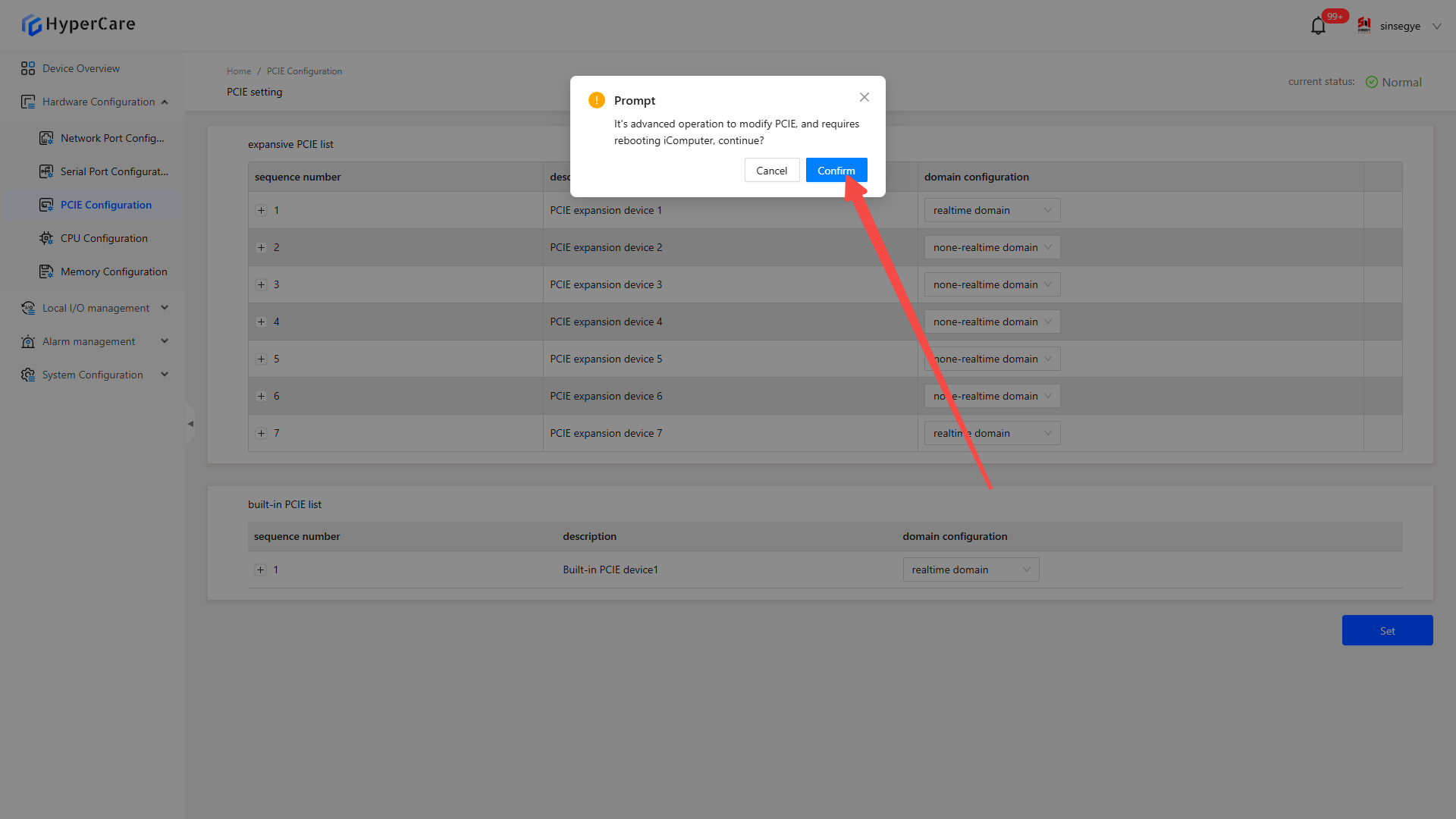
After completing the configuration changes, click the \[Settings] button to display the confirmation prompt window.
After clicking \[Confirm], the device needs to be restarted manually (specific operation method for restart:HyperCare 2.1.4.0 Operation Manual ), and at this time, the PCIE status changes to \[Waiting for Power off to Restart].
f. If an adapted graphics card is connected, the iComputer will default to outputting the desktop display from the external graphics card after startup, while the built-in integrated graphics will no longer output the desktop (the integrated graphics still has output before entering the desktop).
g. If an expansion device applied to a non-real-time domain is unplugged from the iComputer, the extended PCIE list will display the device as \[Missing Device] after the next power-on.
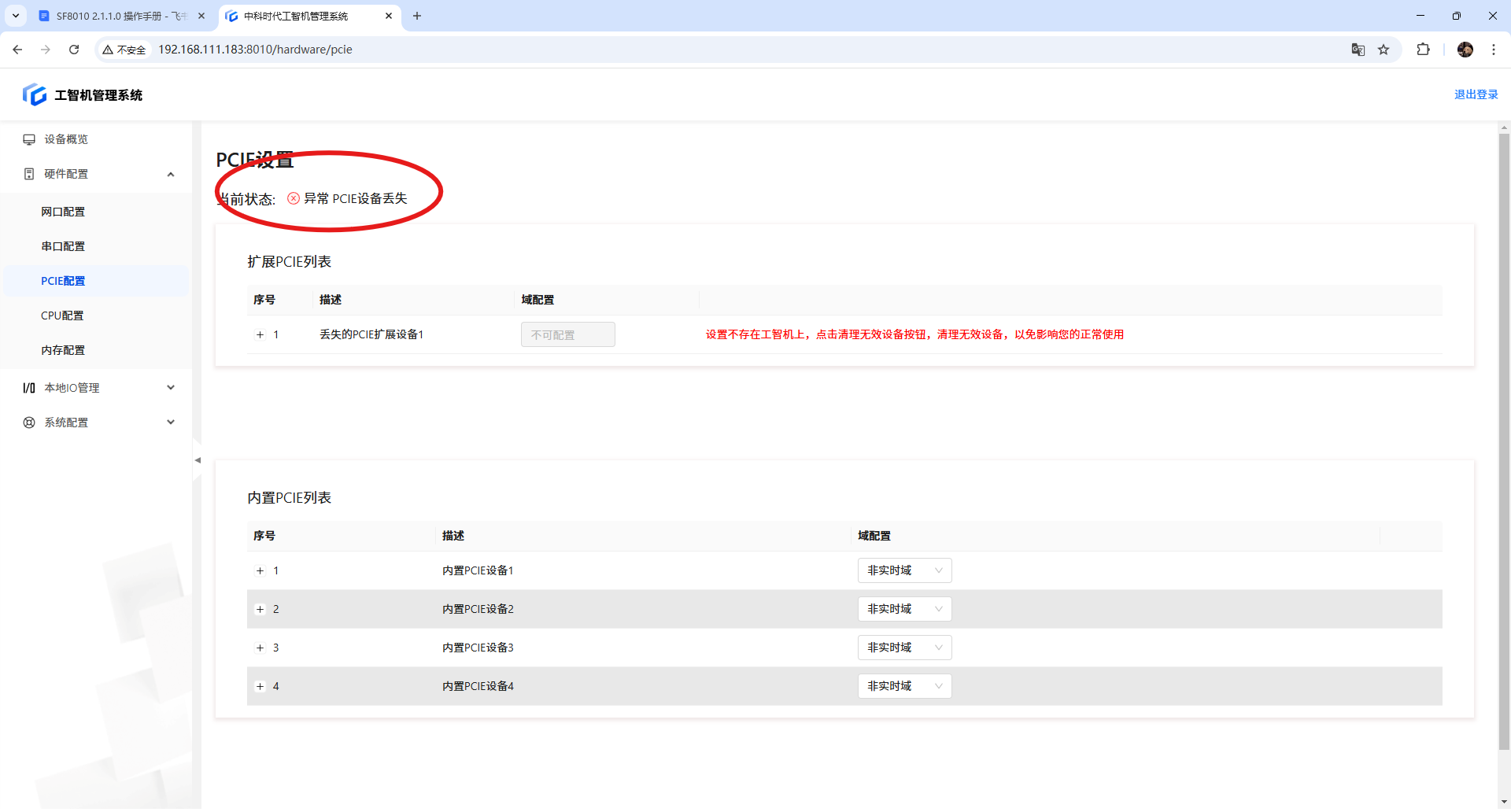
| When there is a \[Missing Device], you must first \[Clean up Invalid Devices] before configuring the PCIE domains for other devices. |
|---|
5.3.4 Important notes
-
The default domain configuration for a newly connected PCIE expansion module is set to \[Non-Real-Time Domain].
-
If an adapted graphics card is connected, the iComputer will default to outputting the desktop display from the external graphics card after startup, while the built-in integrated graphics will no longer output the desktop (the integrated graphics still has output before entering the desktop).
-
When there is a \[Missing Device], you must first \[Clean up Invalid Devices] before configuring the PCIE domains for other devices.
-
When configuring the NIC domain settings of EtherCAT, if you modify it to a non-real-time domain and then change it back to a real-time domain, the NIC will remain in a \[Disabled] state. To use it again, you must reconfigure it.
-
It is recommended to restart immediately after modifying domain configurations. Potential issues may occur if it is not restarted immediately.
-
Please perform configuration modifications in a non-production environment.
6. Hardware Configuration - CPU Configuration
6.1 Scope of Application
It is applicable to all adapted models.
6.2 Function Introduction
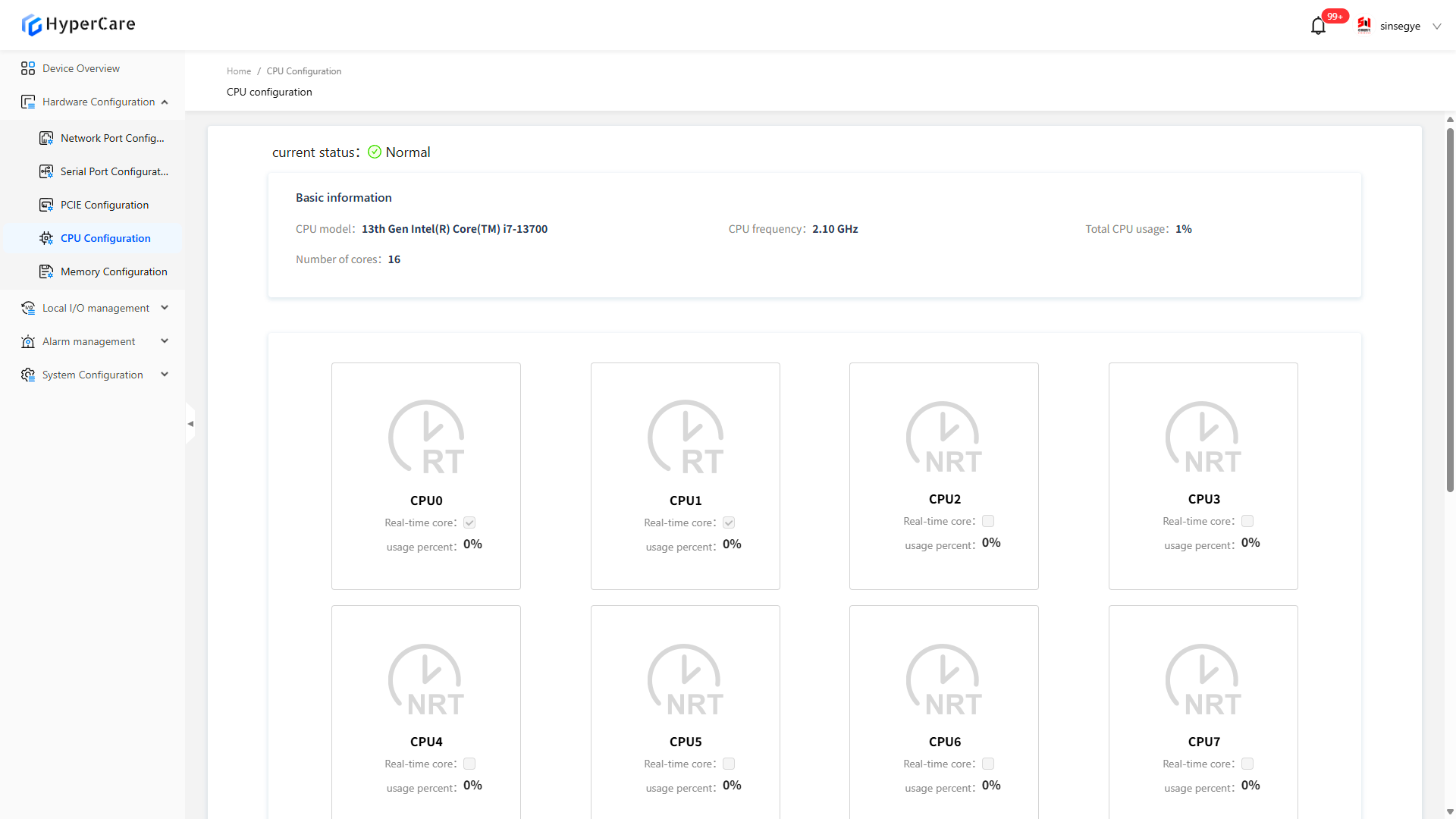
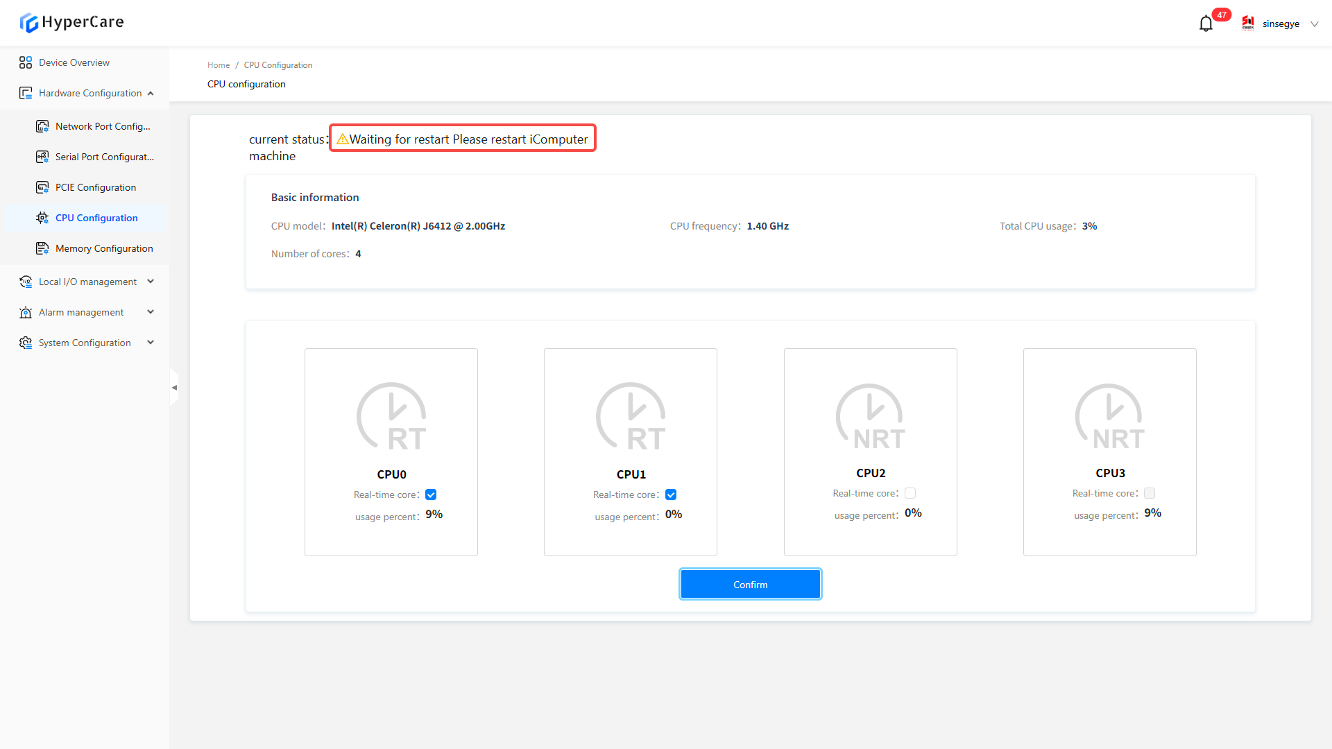
This function is used for CPU core partitioning. \[RT] stands for real-time domain core partitioning. \[NRT] stands for non-real-time domain core partitioning.
6.3 Usage Details
6.3.1 Enter the page
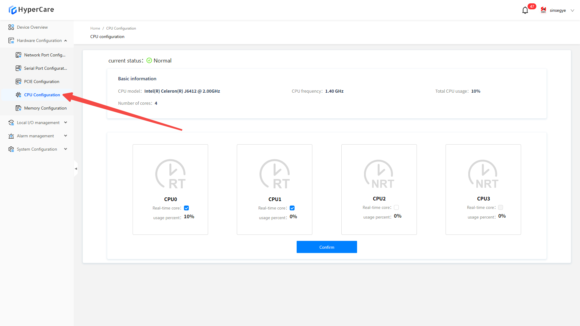
6.3.2 Modification of cores
Check the CPU box to assign it to real-time domain; uncheck it to assign it to non-real-time domain
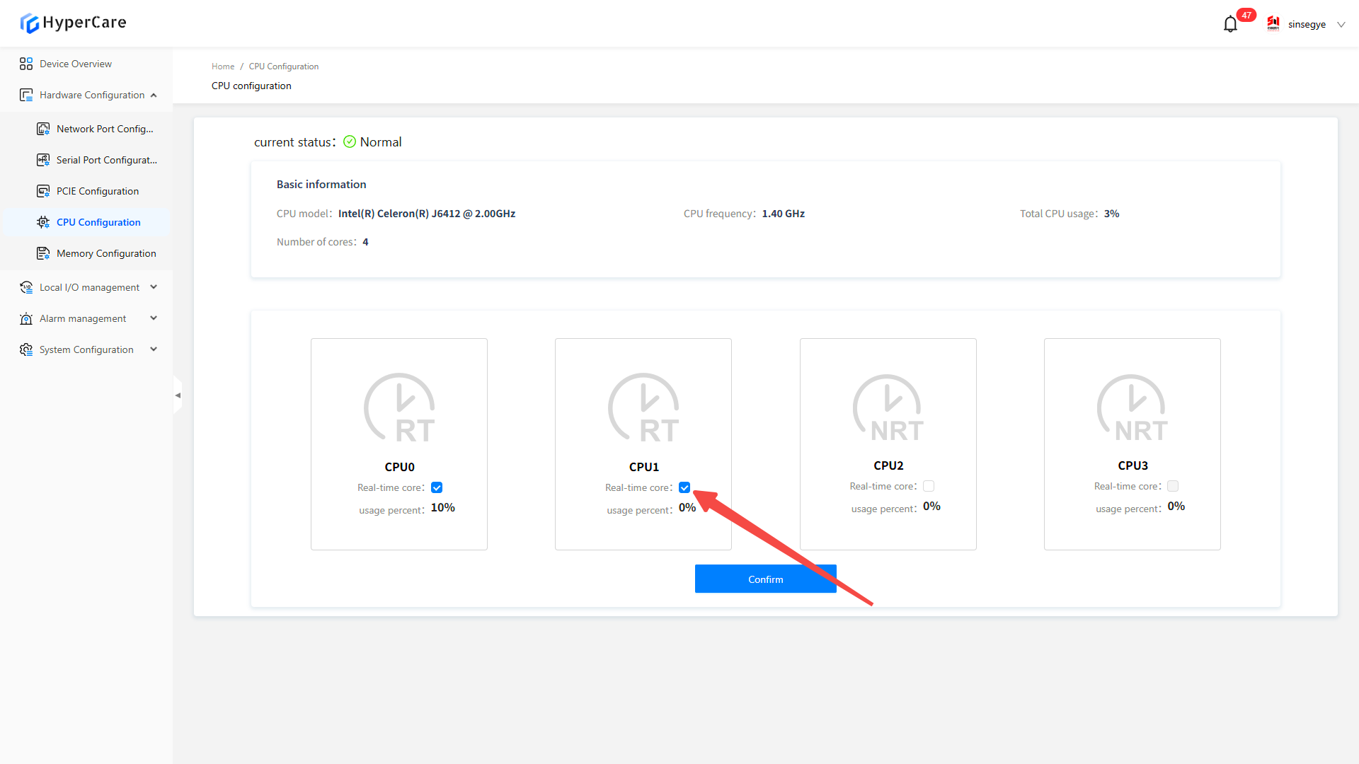
After completing the multi-core configuration, click the \[OK] button.
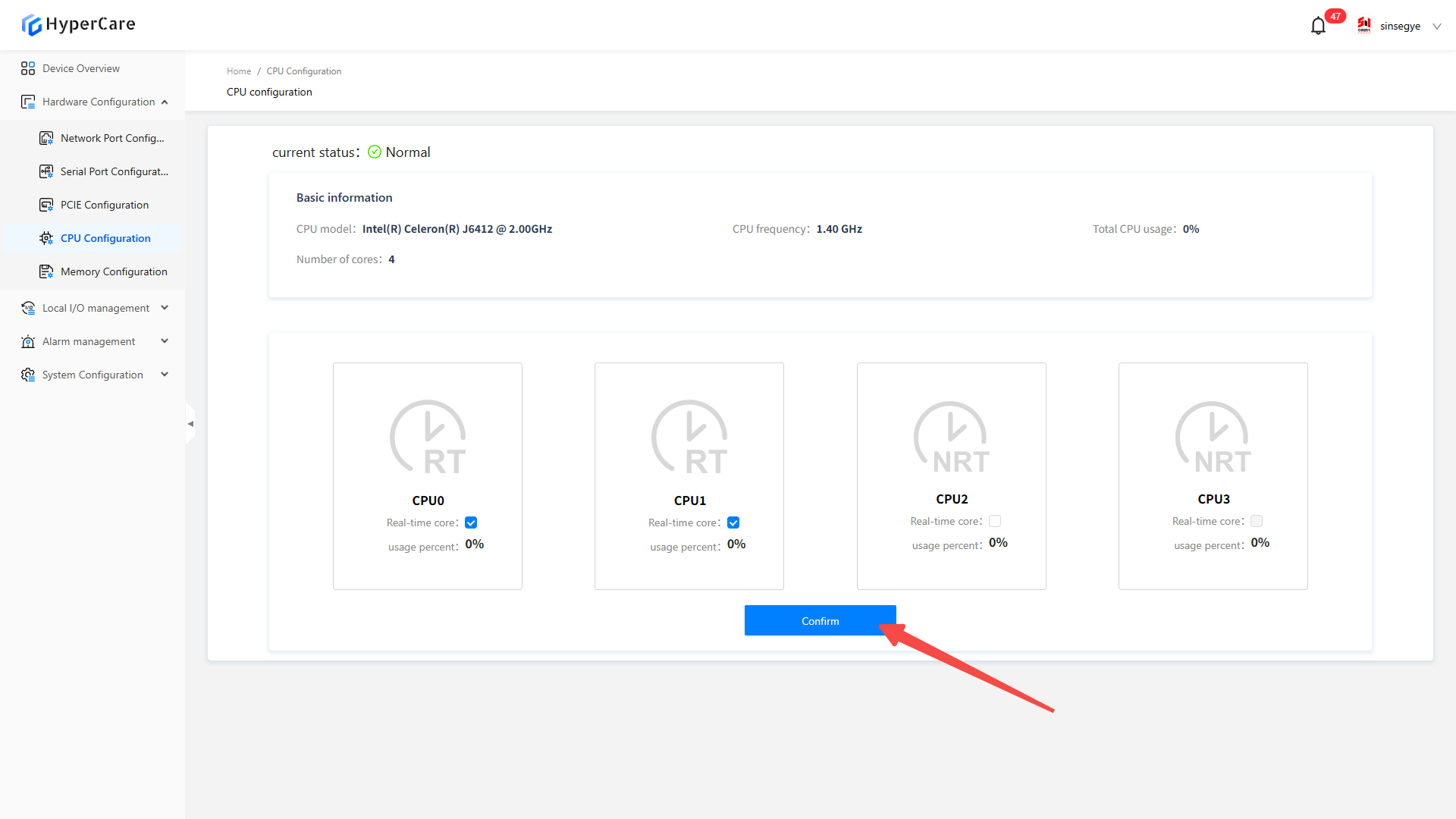
The system will display a confirmation prompt. Click \[Confirm] to enter the waiting page.
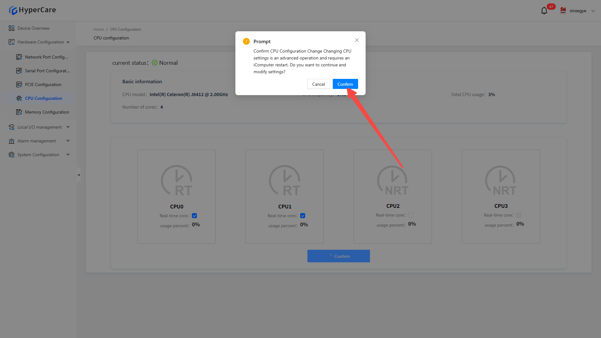
After completing the configuration modification, you need to manually restart the device (specific operation method for restart: HyperCare 2.1.4.0 Operation Manual ), and at this time, the CPU status changes to \[Waiting for Restart].
6.3.3 Important notes
-
After modifying the CPU configuration, it is recommended to restart the system immediately. Potential issues may occur if it is not restarted immediately.
-
When modifying CPU configurations in a non-production environment, care must be taken to avoid impacting the system stability.
7. Hardware Configuration - Memory Configuration
7.1 Scope of Application
| SP series | SX2 series | SX5232 series |
|---|---|---|
| SP7010-1211 | SX2133 Type II | |
| SP7020-2231 | ||
| SP7022-2231 | ||
| SP5040-3331 | ||
| SP5040-4331 |
7.2 Function Introduction
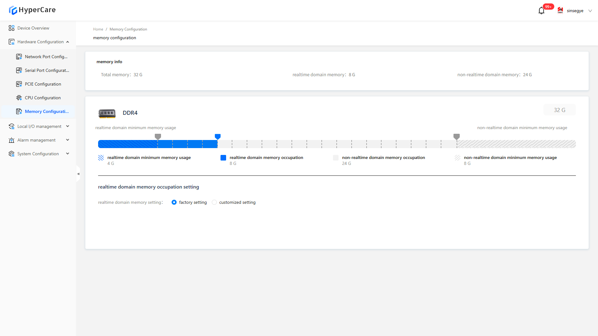
This function is used to manage memory allocation between real-time and non-real-time domains.
7.3 Usage Details
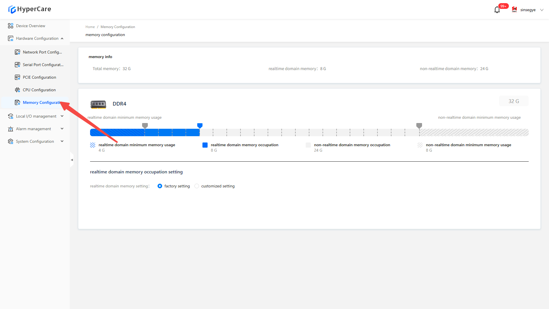
7.3.1 Enter the page
7.3.2 Modify memory
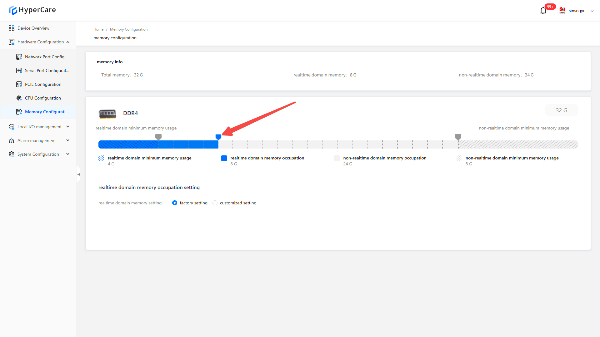
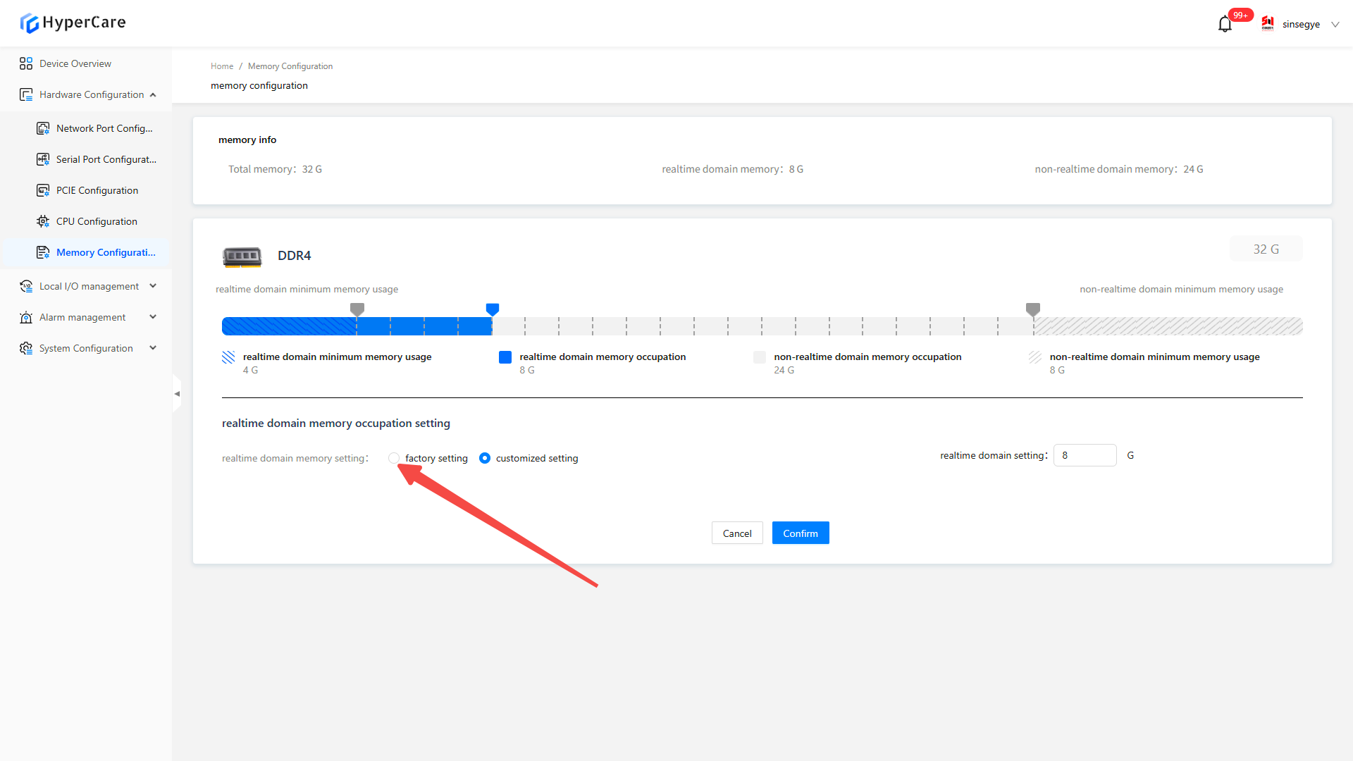
Drag the blue slider to modify memory allocation.
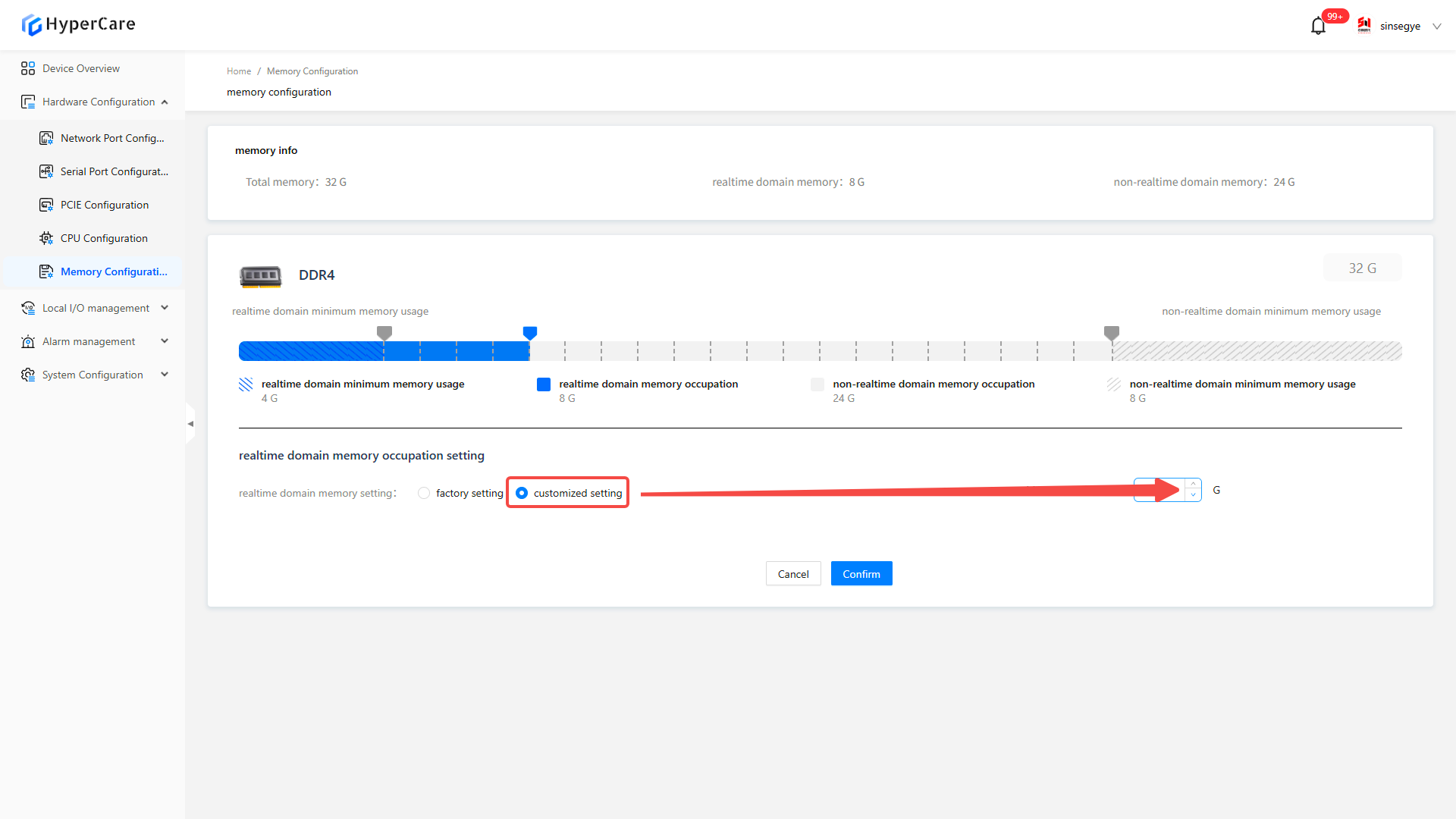
After selecting \[Custom Settings], modify the memory by entering numbers.
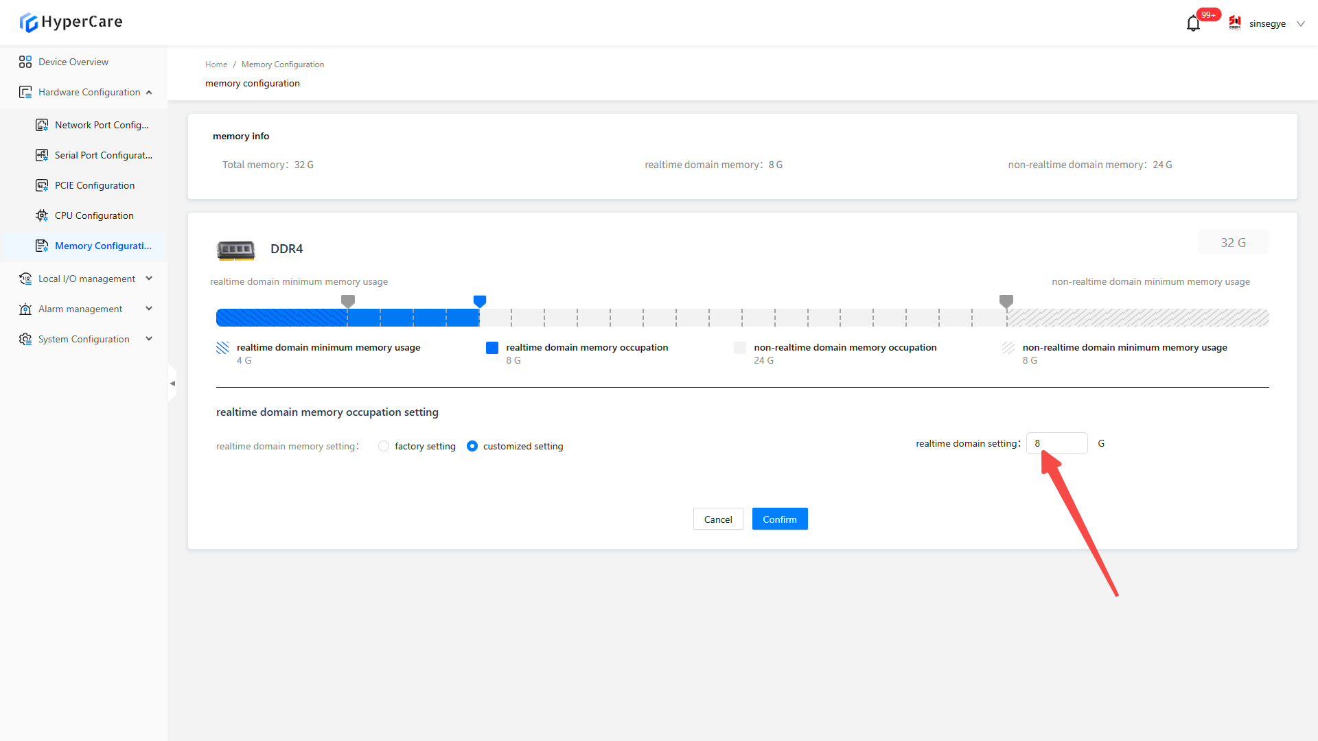
After selecting \[Custom Settings], adjust the memory by clicking the arrows.
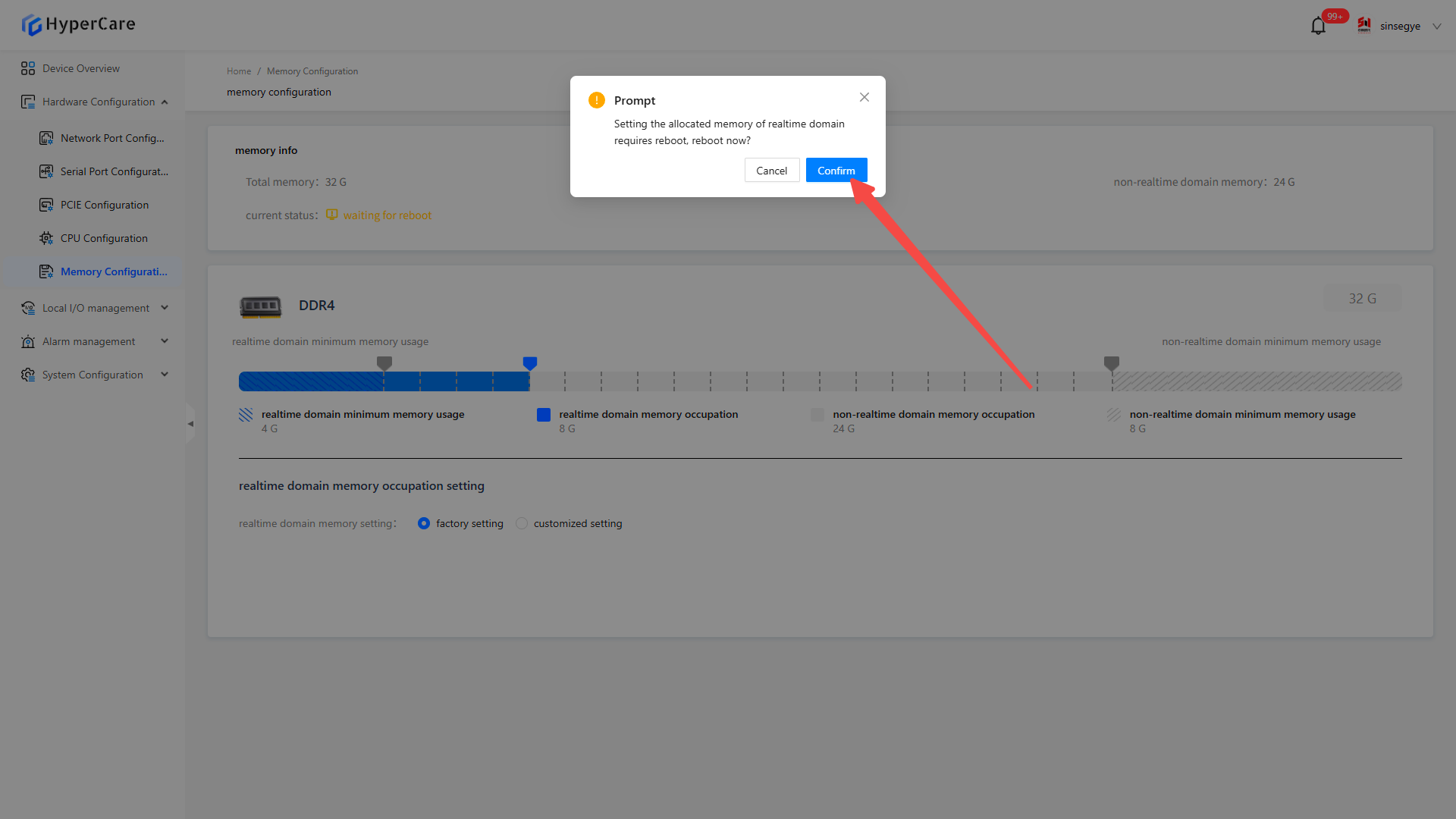
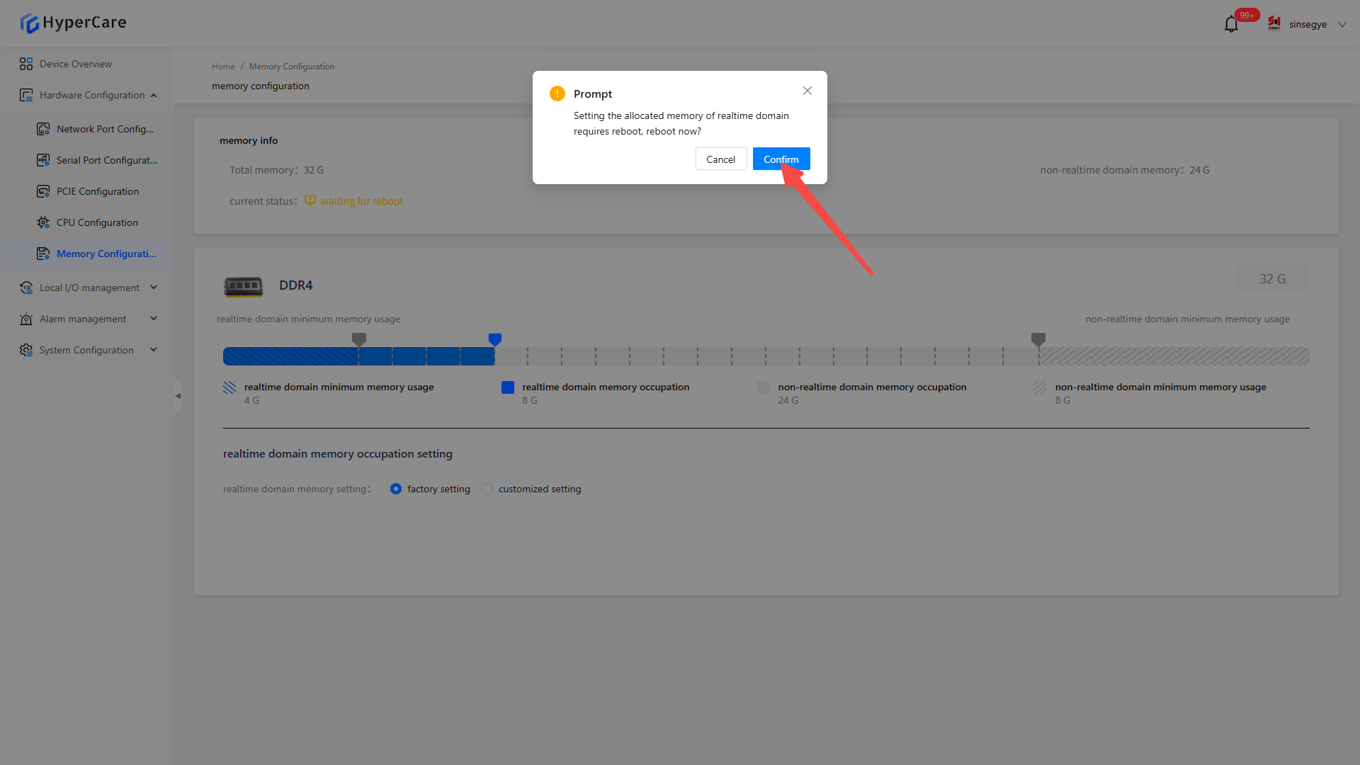
After completing memory modification, click the \[OK] button. The system will display a confirmation prompt.
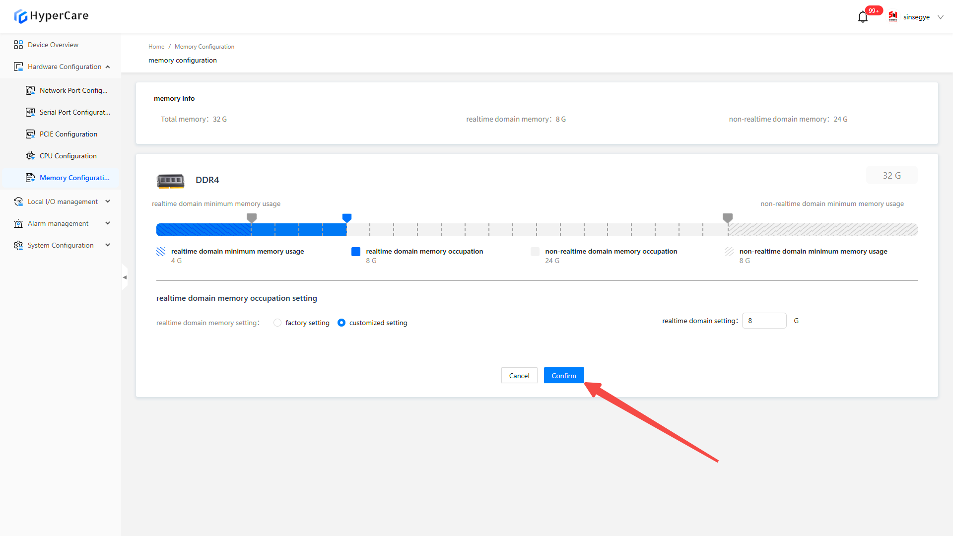
Click \[Confirm] to enter the waiting page.
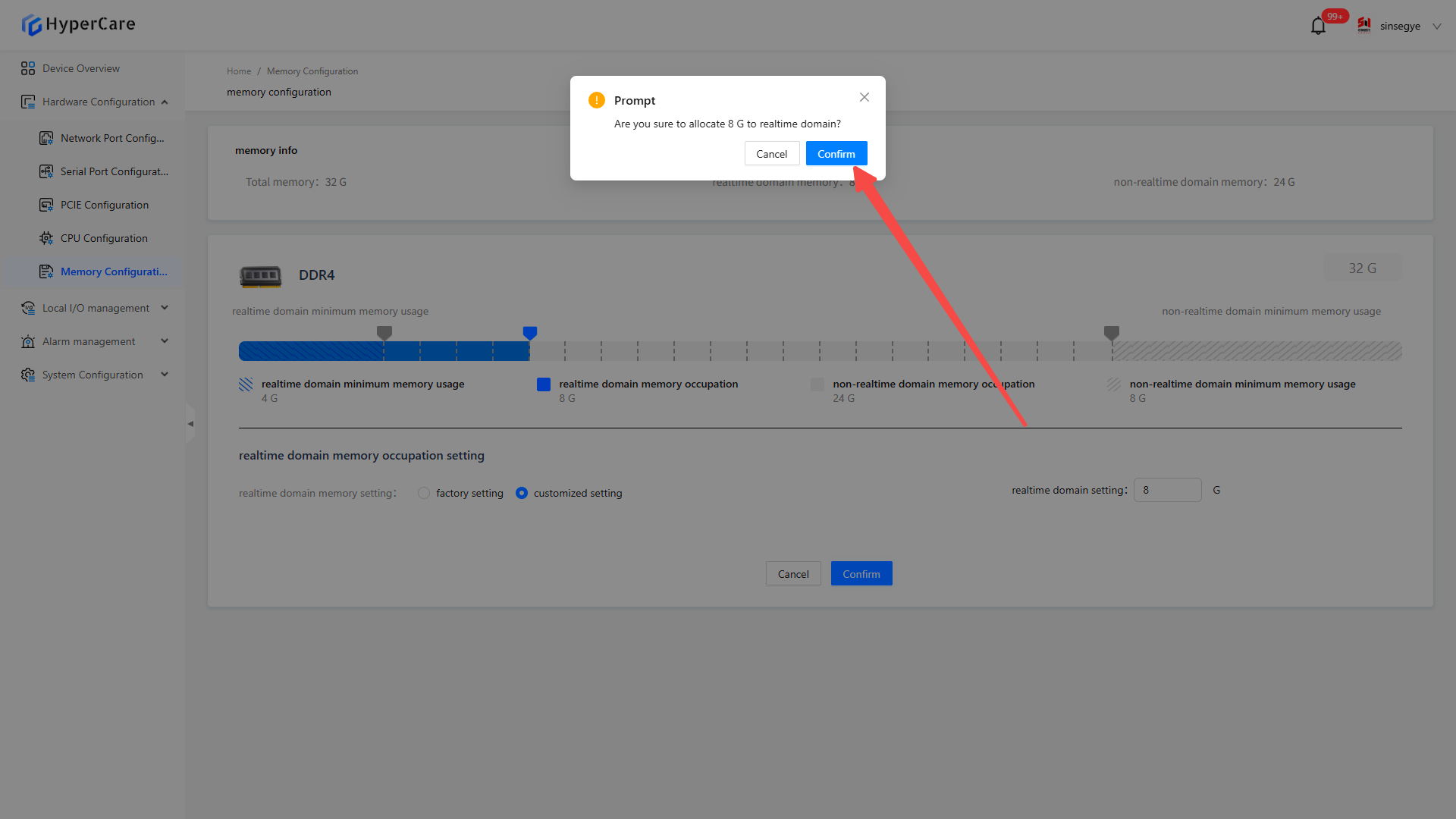
After the waiting page loads, a restart prompt window will pop up. You can choose to click the \[Confirm] button to restart immediately to restart.
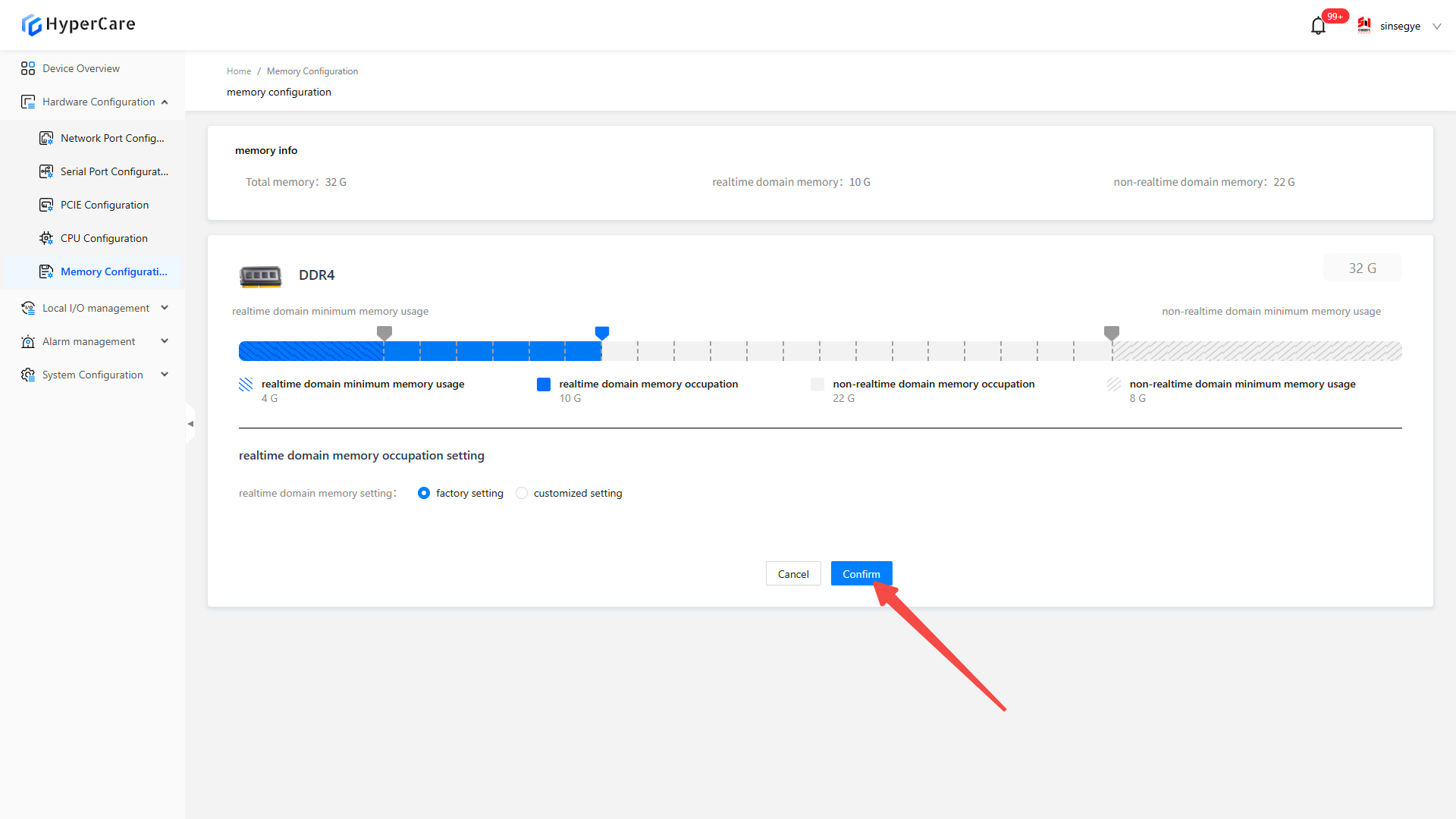
7.3.3 Restore factory settings
After clicking the \[Factory Settings] button
Click the \[OK] button. The system will display a confirmation prompt.
Click \[Confirm] to enter the waiting page.
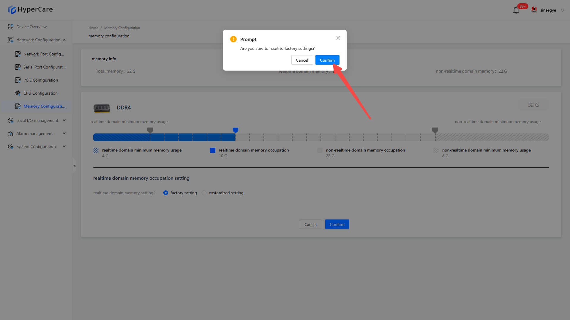
After the waiting page loads, a restart prompt window will pop up. You can choose to click the \[Confirm] button to restart immediately.
7.3.4 Important notes
-
When modifying the memory, pay attention to the thresholds of \[Minimum Memory Used by Real-time Domain] and \[Minimum Memory Used by Non-real-time Domain]. Memory cannot be modified if the value is lower than the thresholds.
-
It is recommended to restart the system immediately after modifying the memory configuration. Potential issues may occur if it is not restarted immediately.
-
When modifying the memory configuration in a non-production environment, care must be taken to avoid impacting the system stability.
8. Local IO Management - Local IO Mode Selection
8.1 Scope of Application
| SX58 series | SX51XX-10XX series | SX51XX-11XX series | SX51XX-20XX series | SX52 series | SX2 series |
|---|---|---|---|---|---|
| SX5820-0001 | SX5132-10XX | SX5132-11XX | SX5132-20XX | SX5232-2112 | SX2133 Type I |
| SX5820-0002 | SX5164-10XX | SX5164-11XX | SX5164-20XX | SX2133 Type II | |
| SX5820-0101 | SX5100-10XX | SX5100-11XX | SX5100-20XX | ||
| SX5820-0102 |
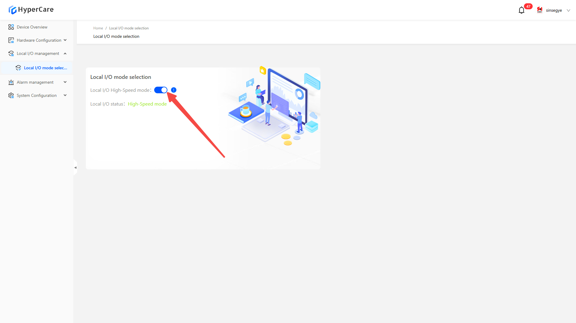
8.2 Function Introduction
When this function is enabled, local IO will be switched to the high-speed mode.
8.3 Usage Details
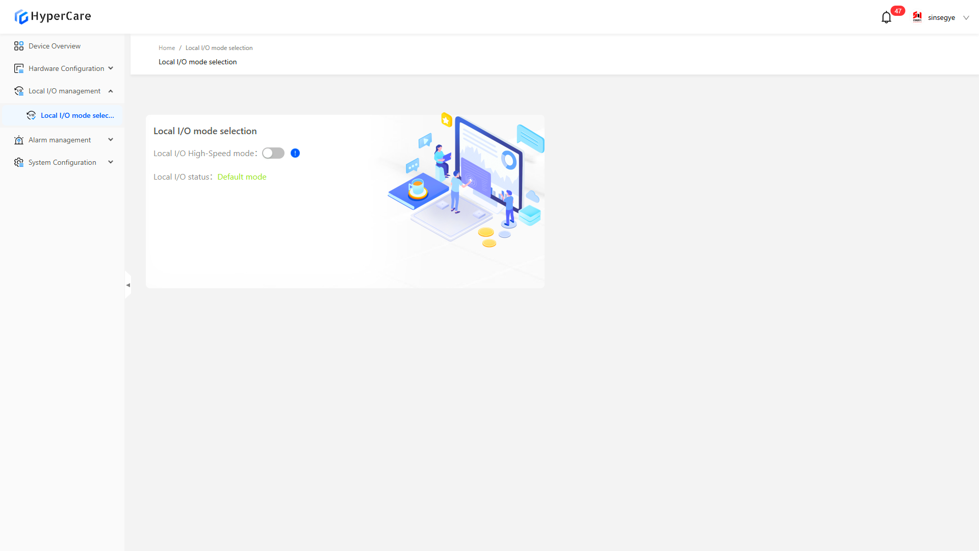
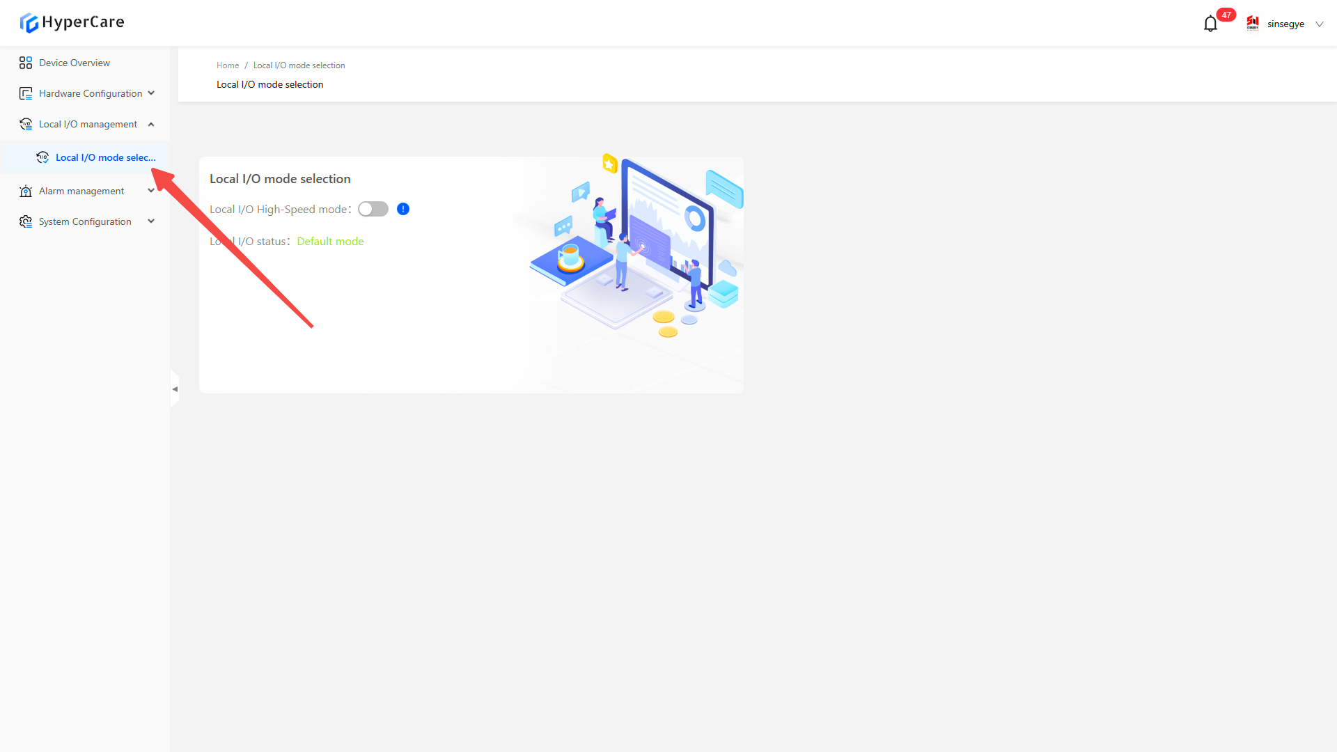
8.3.1 Enter the page
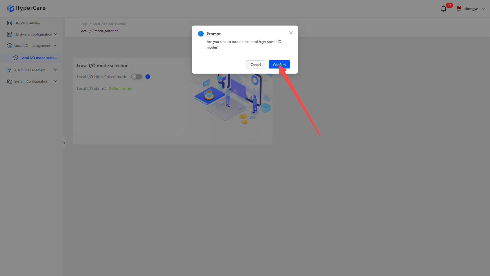
8.3.2 Enable local IO high-speed mode
After clicking the \[Local IO High-Speed Mode] switch, a confirmation prompt will pop up.
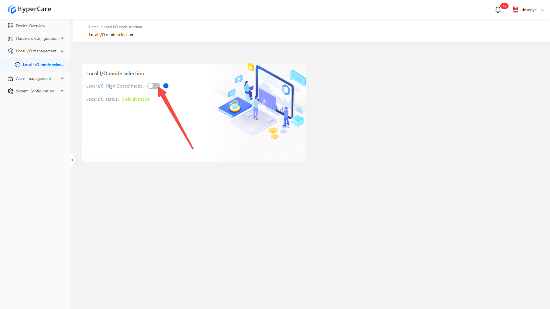
Clicking the \[Confirm] button will enable local IO mode.
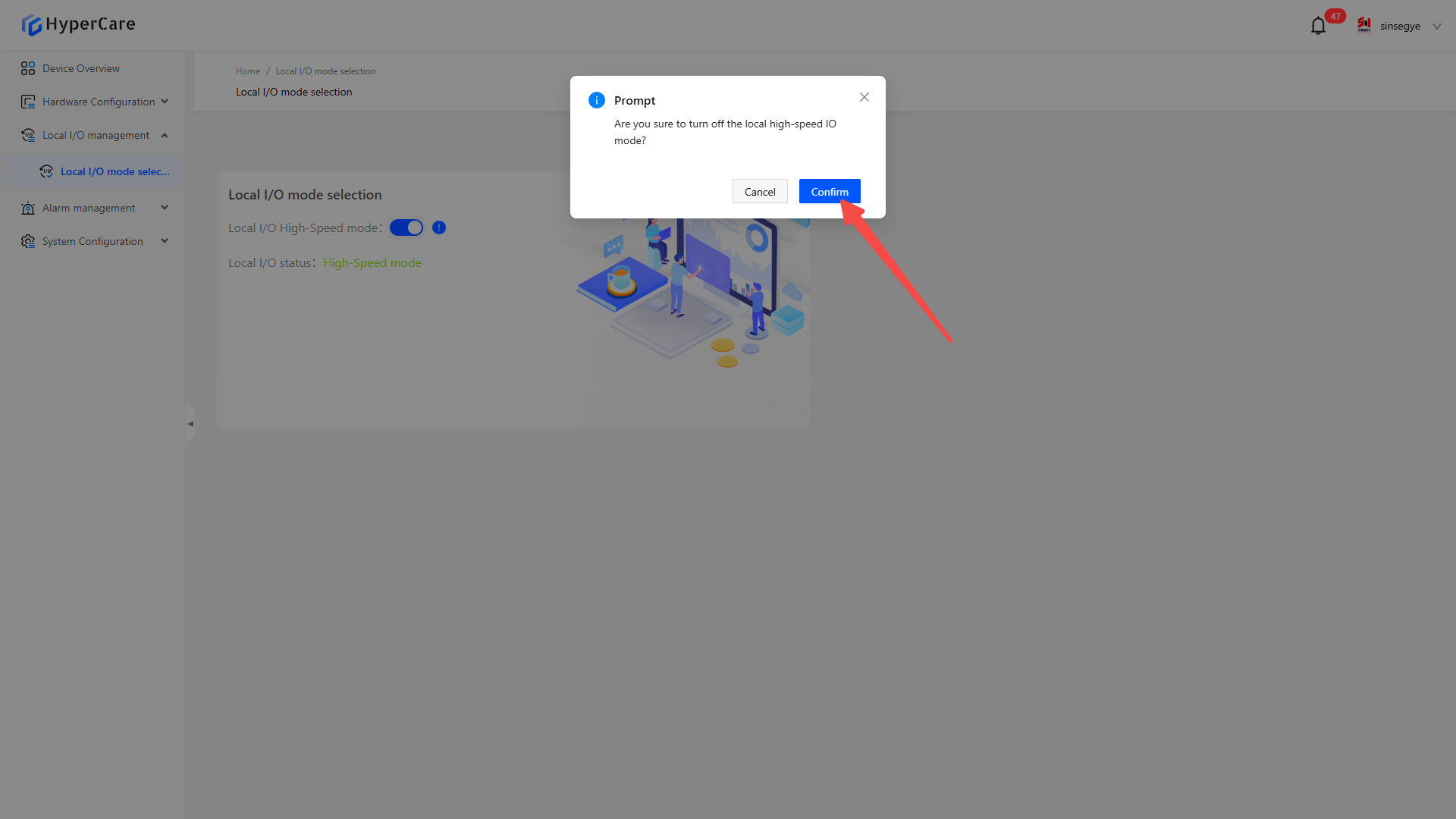
8.3.3 Disable local IO high-speed mode
After clicking the \[Local IO High-Speed Mode] switch, a confirmation prompt will pop up.
Clicking the \[Confirm] button will disable local IO mode.
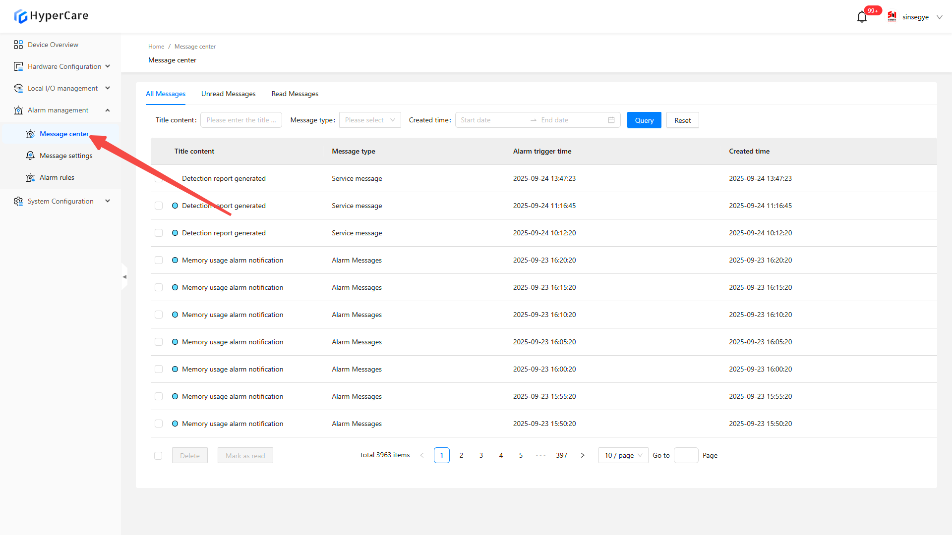
9. Alarm Management - Message Center
9.1 Scope of Application
It is applicable to all adapted models.
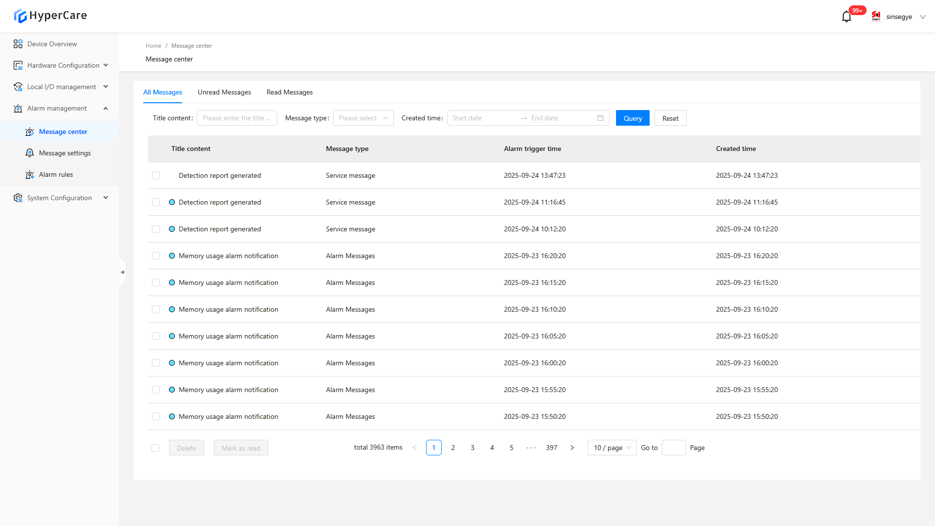
9.2 Function Introduction
This function is used for classification and screening, composite condition query, and sequential display of alarm messages.
9.3 Usage Details
9.3.1 Enter the page
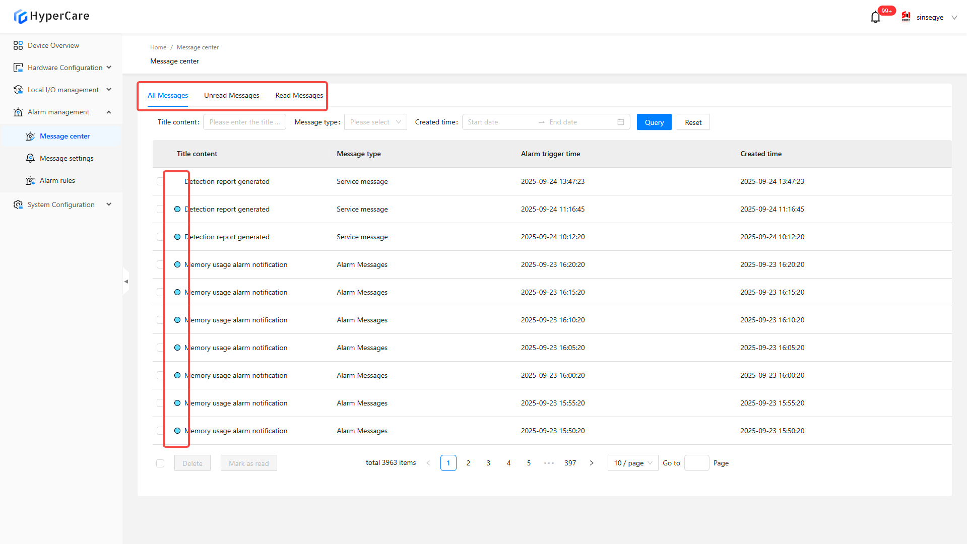
9.3.2 Tab switching
-
\[All Messages] displays all message entries
-
\[Unread Messages] only shows unread messages (marked with ●)
-
\[Read Messages] only displays processed messages
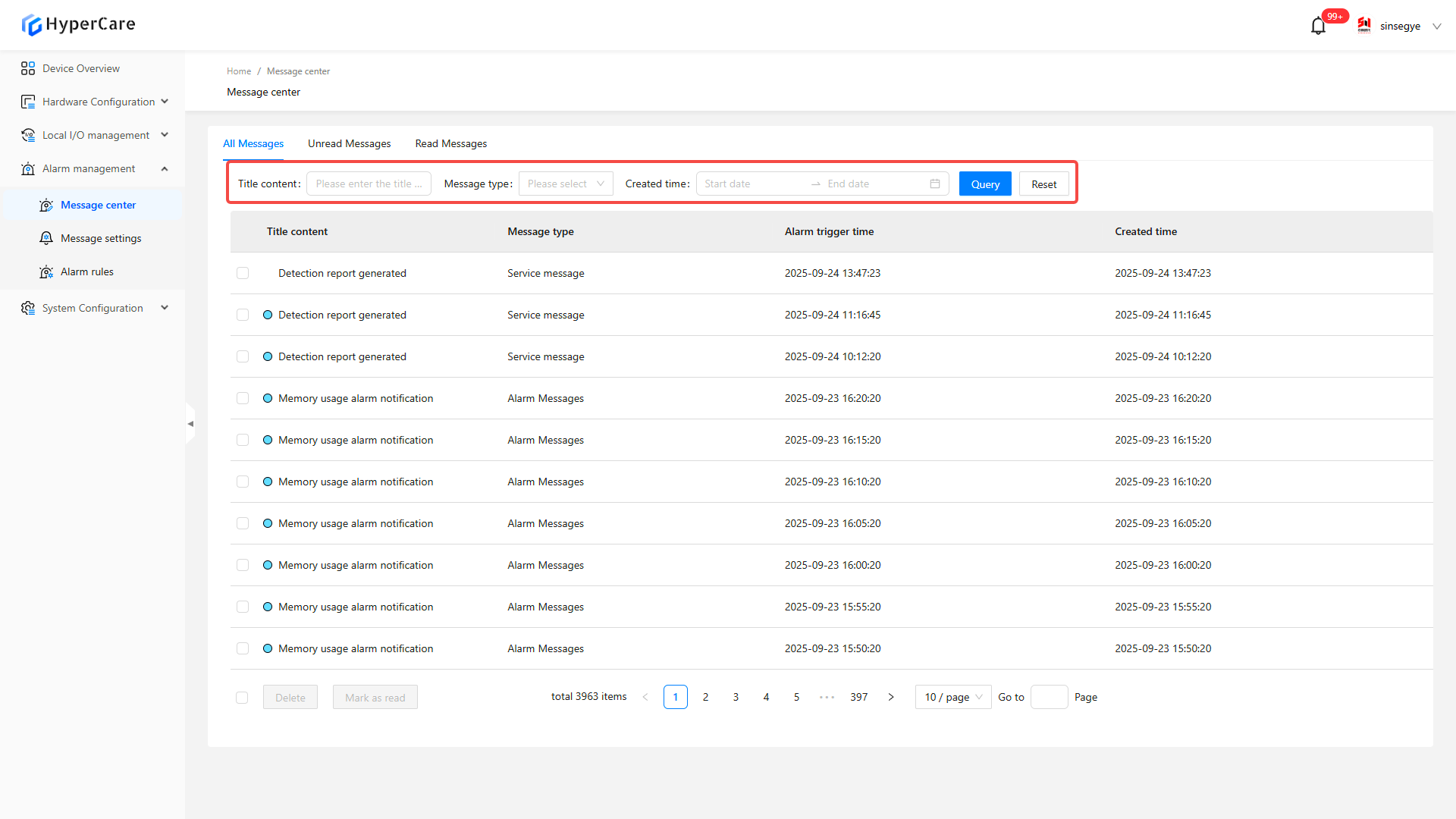
9.3.3 Message screening and query
Carry out query though title content, message type, and creation time. Click the blue \[Query] button to apply the screening conditions. Click the white \[Reset] button to clear all screening conditions.
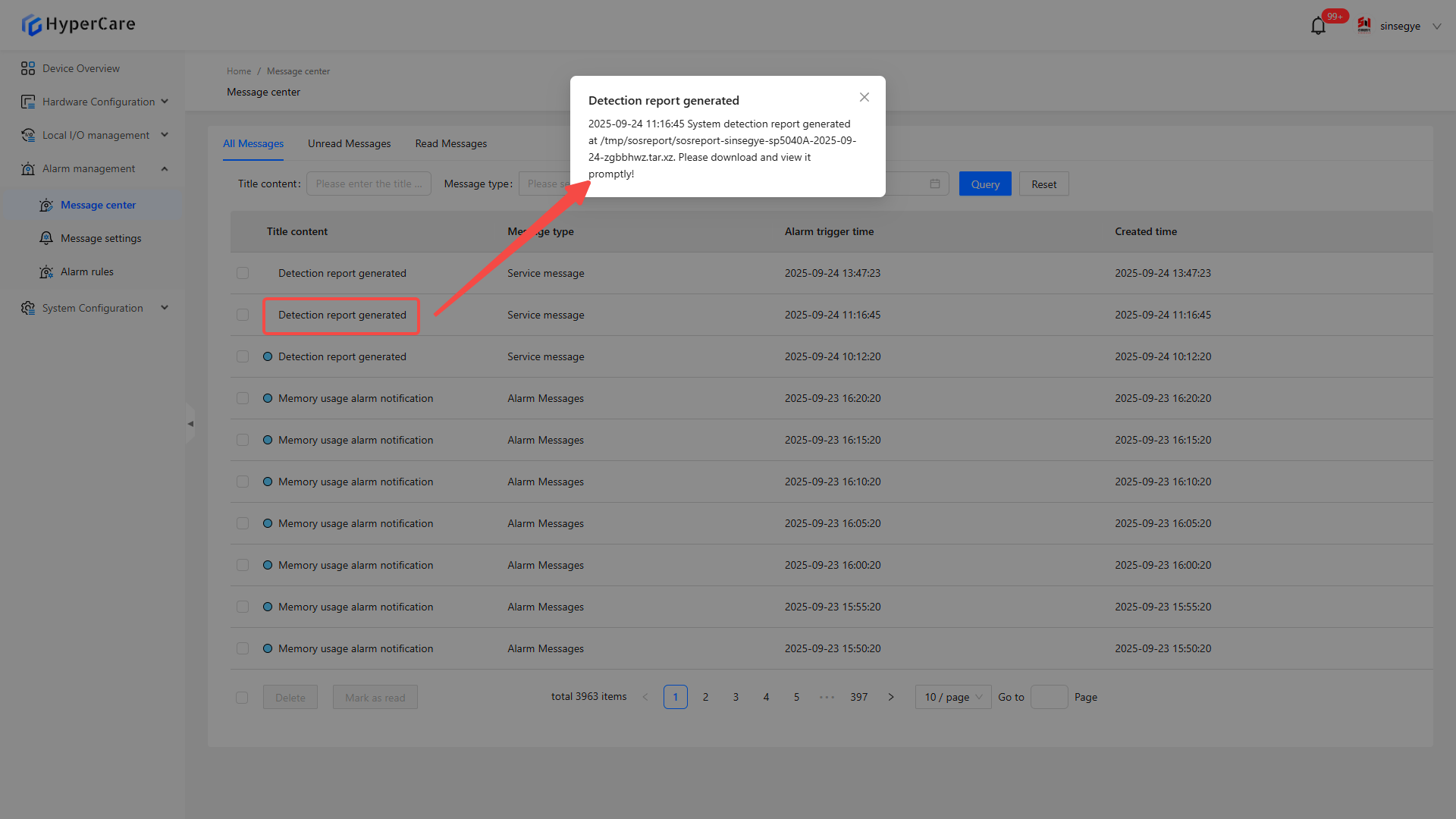
9.3.4 Read message
Click the \[Message Title]. Automatically mark it as read. The message will be moved from the "Unread" tab to the "Read" tab.
9.3.5 Message management
Check the checkbox on the left side of the message
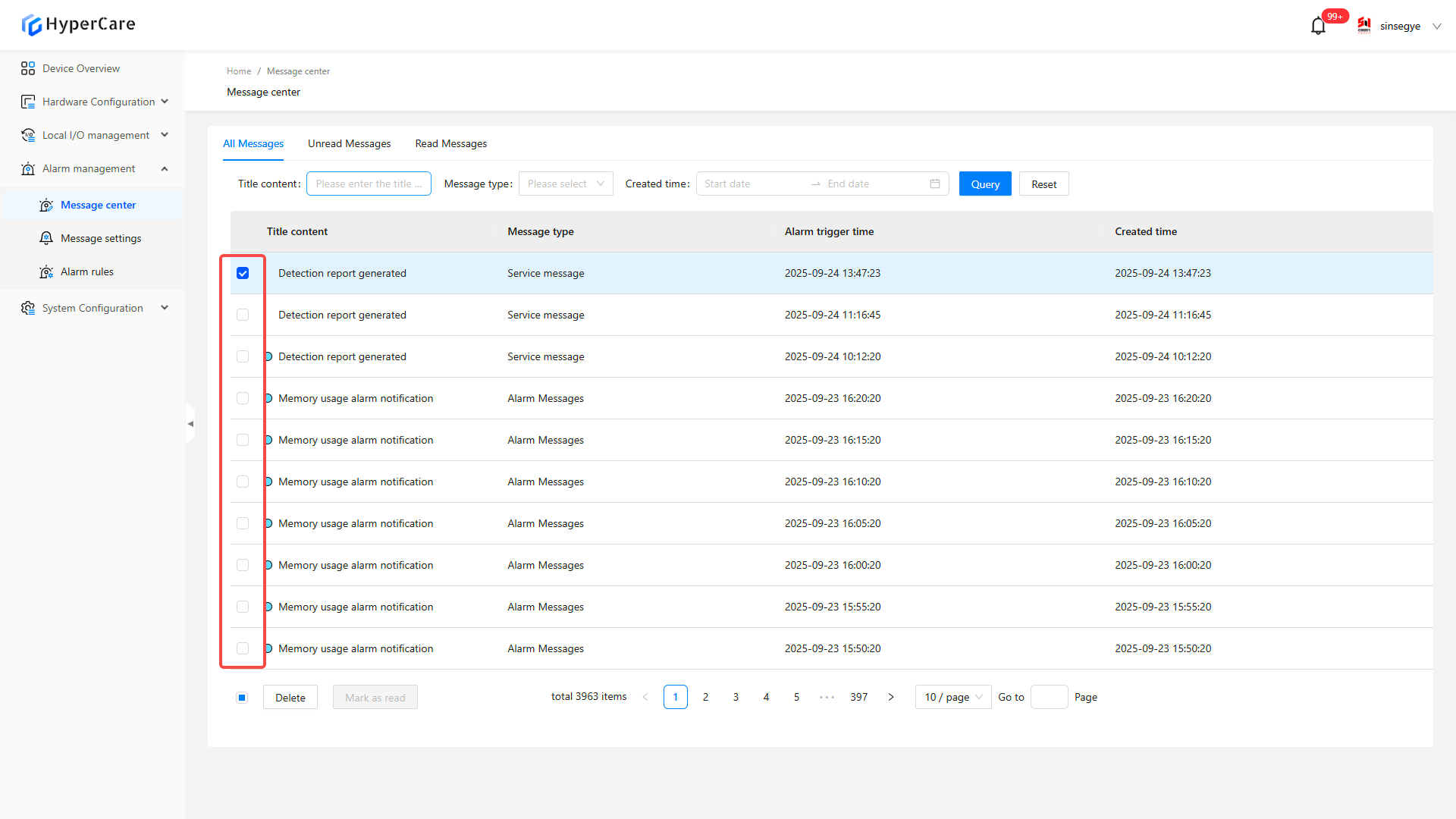
Click \[Select All] at the left corner to select all messages on the current page
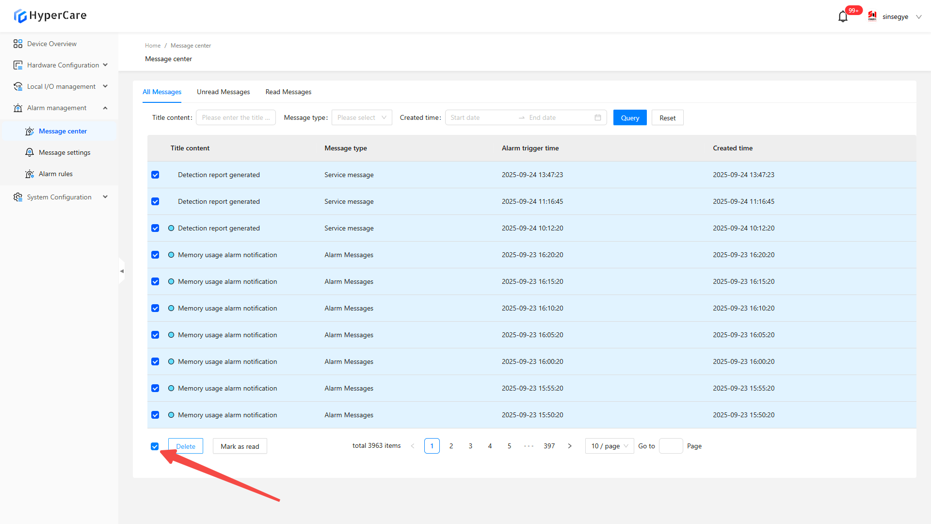
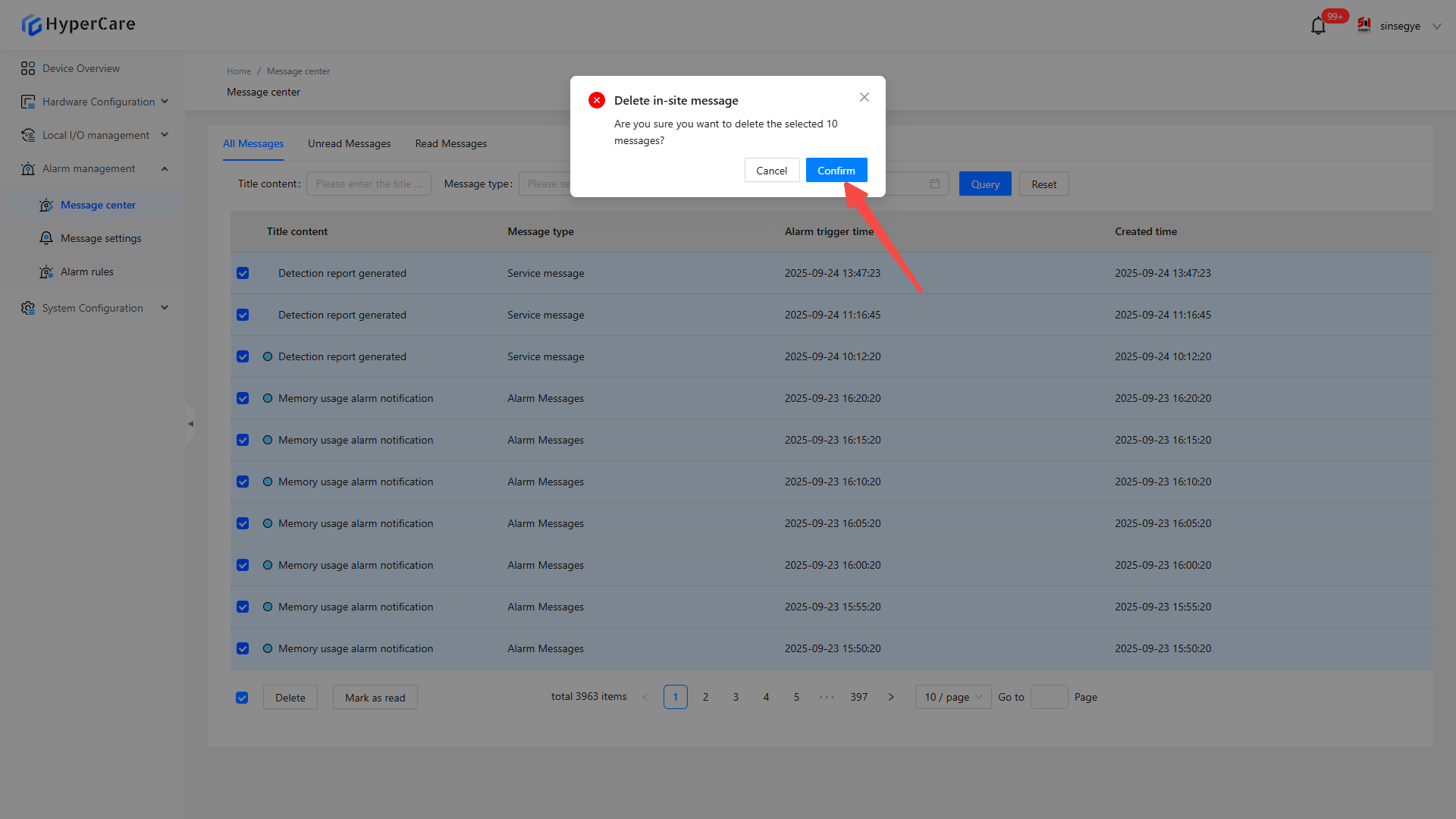
Click \[Delete] to delete the selected messages

Click \[Confirm] to perform the operation
Click \[Mark as read] to mark the unread message as read
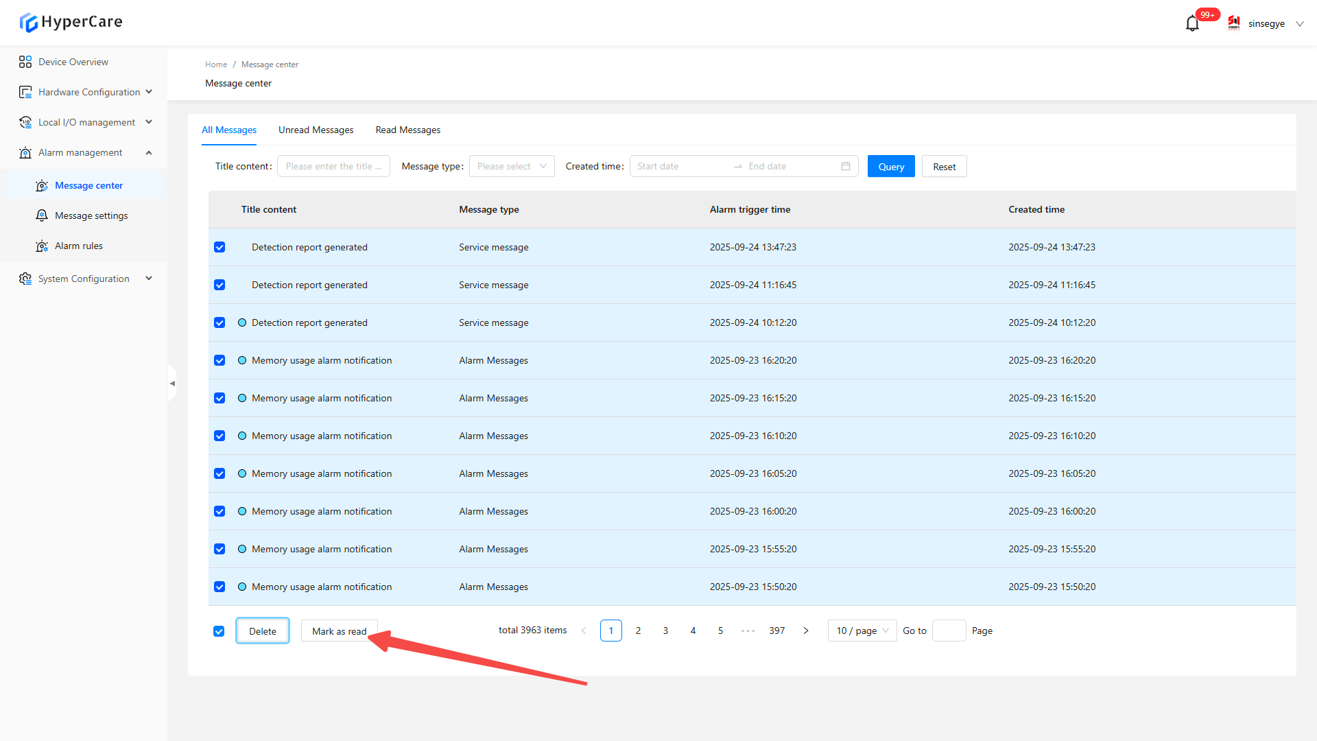
Click \[Confirm] to perform the operation

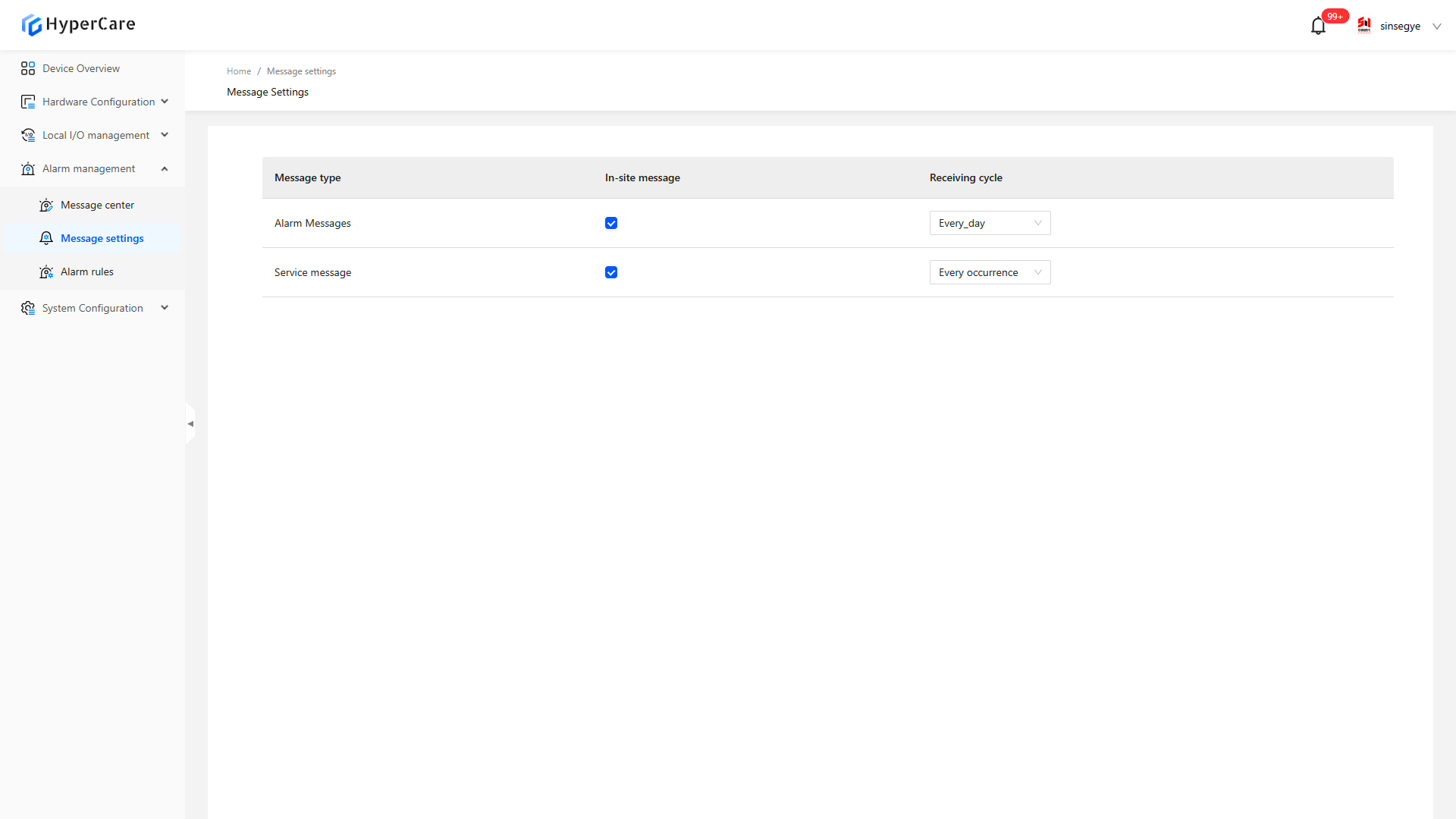
10. Alarm Management - Message Settings
10.1 Scope of Application
It is applicable to all adapted models.
10.2 Function Introduction
This function is used for alarm rule configuration, and it supports customized receiving methods and cycles.
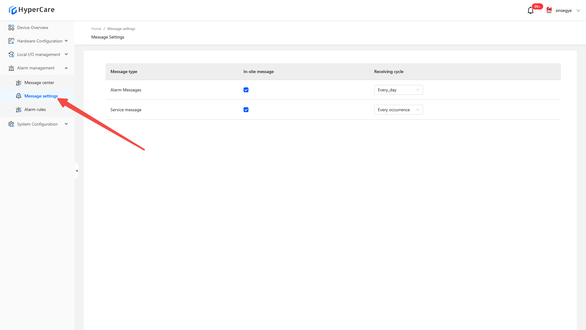
10.3 Usage Details
10.3.1 Enter the page
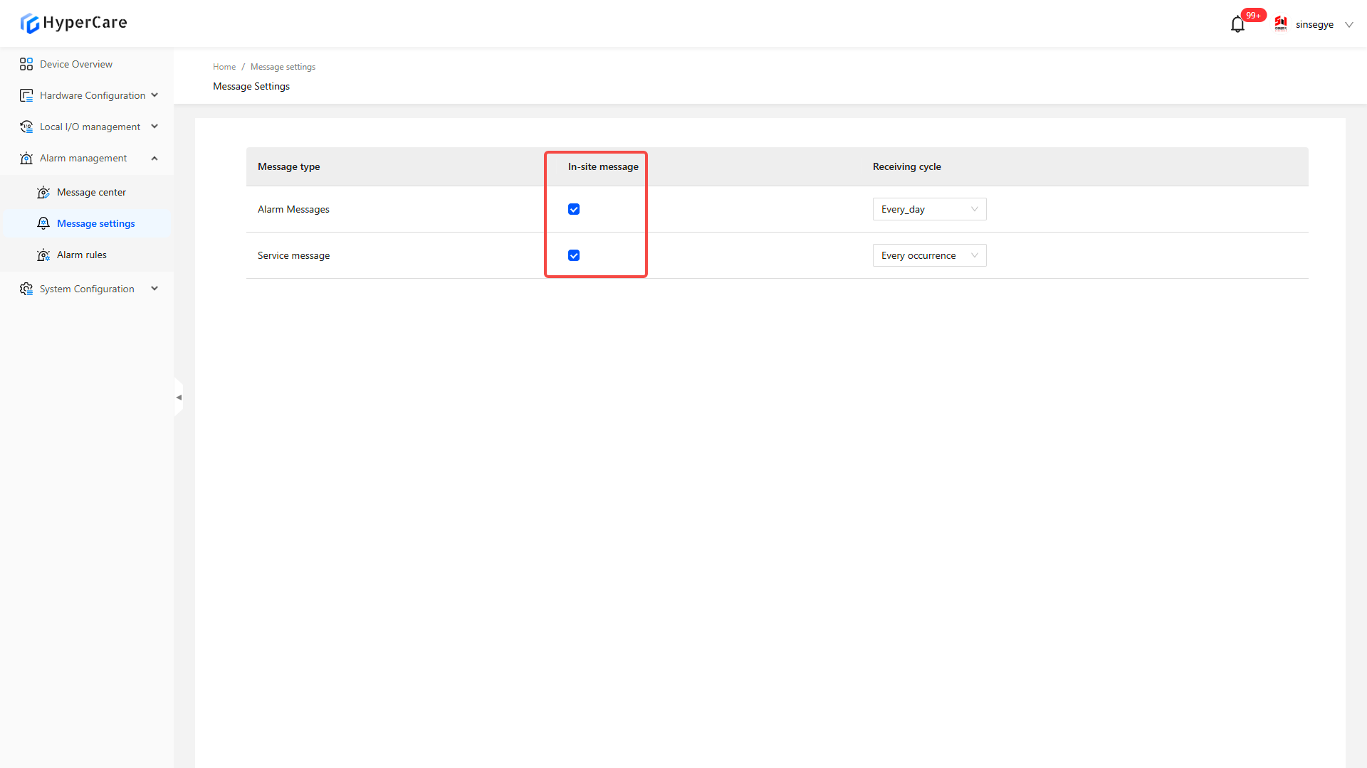
10.3.2 Receiving method settings
Select a receiving method (it currently only supports in-site messages)
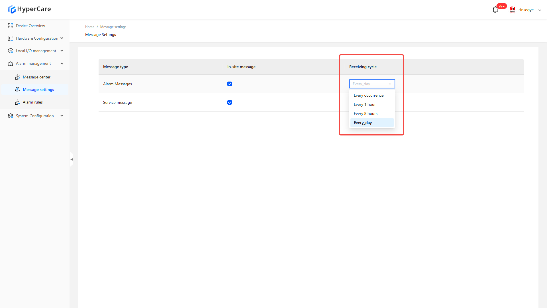
10.3.3 Receiving cycle settings
| Option | Effective Rules |
|---|---|
| Every occurrence (default) | Real-time alarm push |
| Every 1 hour | Merge and push same-type alarms once within 1 hour |
| Every 8 hours | Merge and push same-type alarms once within 8 hours |
| Every day | Merge and push same-type alarms once within 24 hours |
 |
11. Alarm Management - Alarm Rules
11.1 Scope of Application
It is applicable to all adapted models.
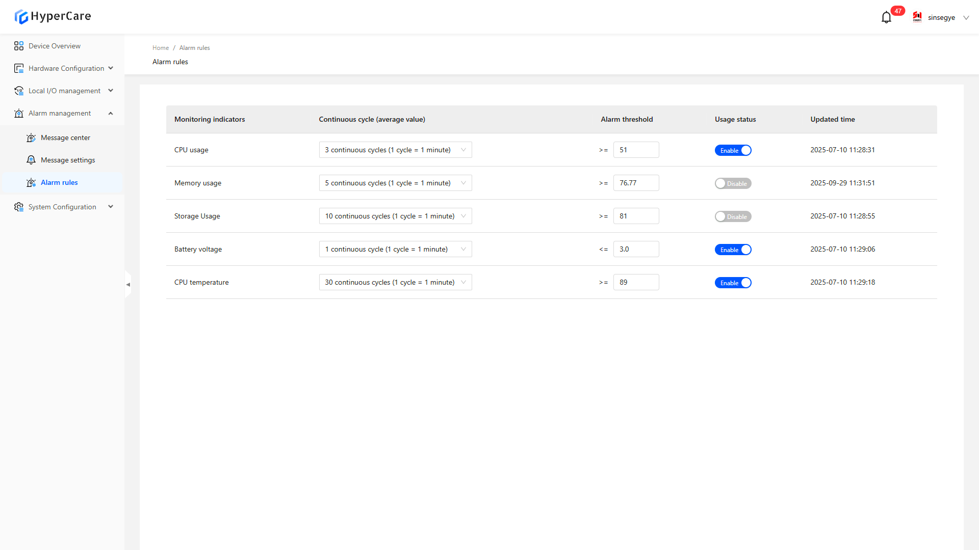
11.2 Function Introduction
This function is used to set the threshold value for monitoring key metrics such as CPU, memory, storage, and temperature.
11.3 Usage Details
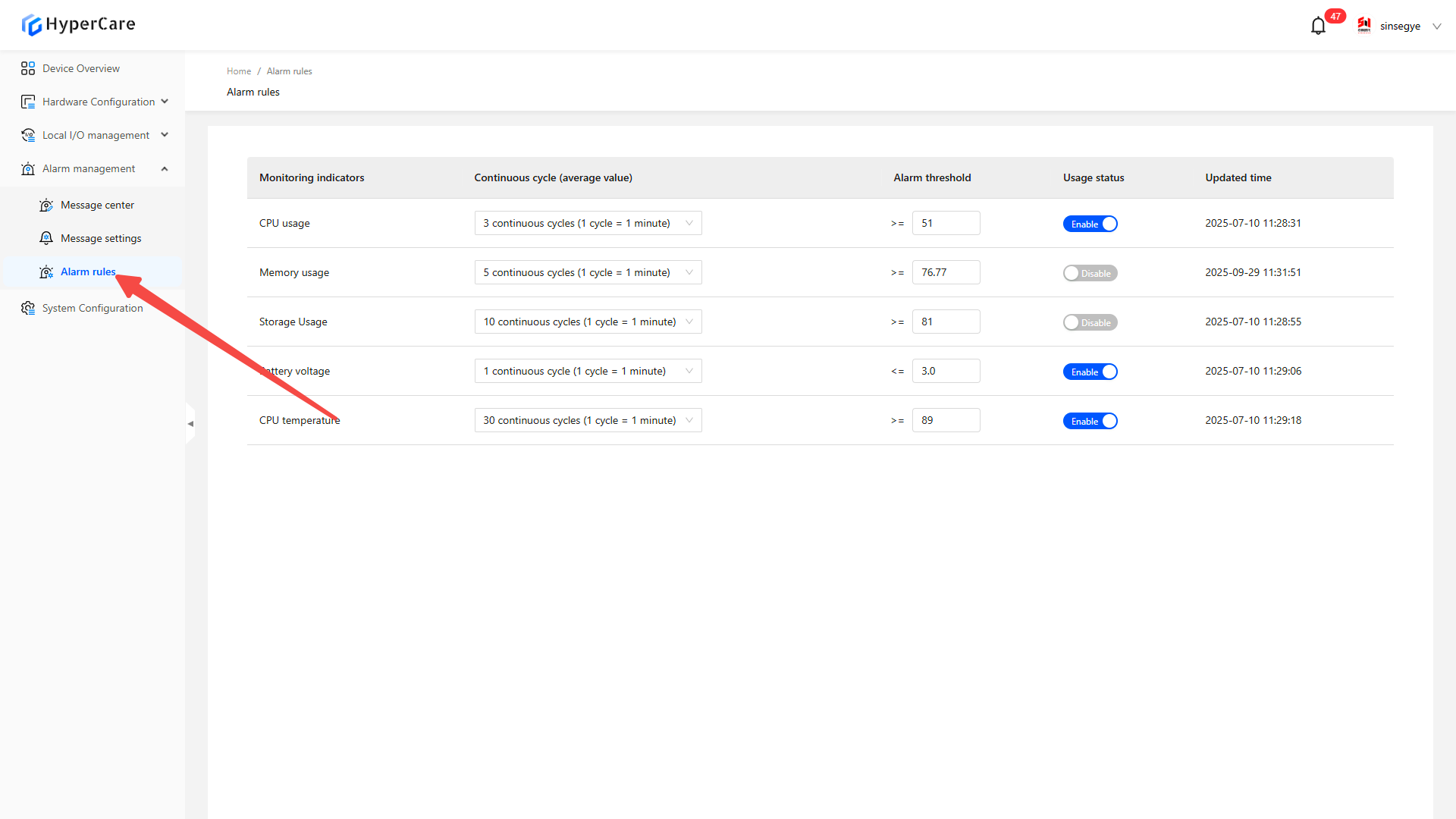
11.3.1 Enter the page
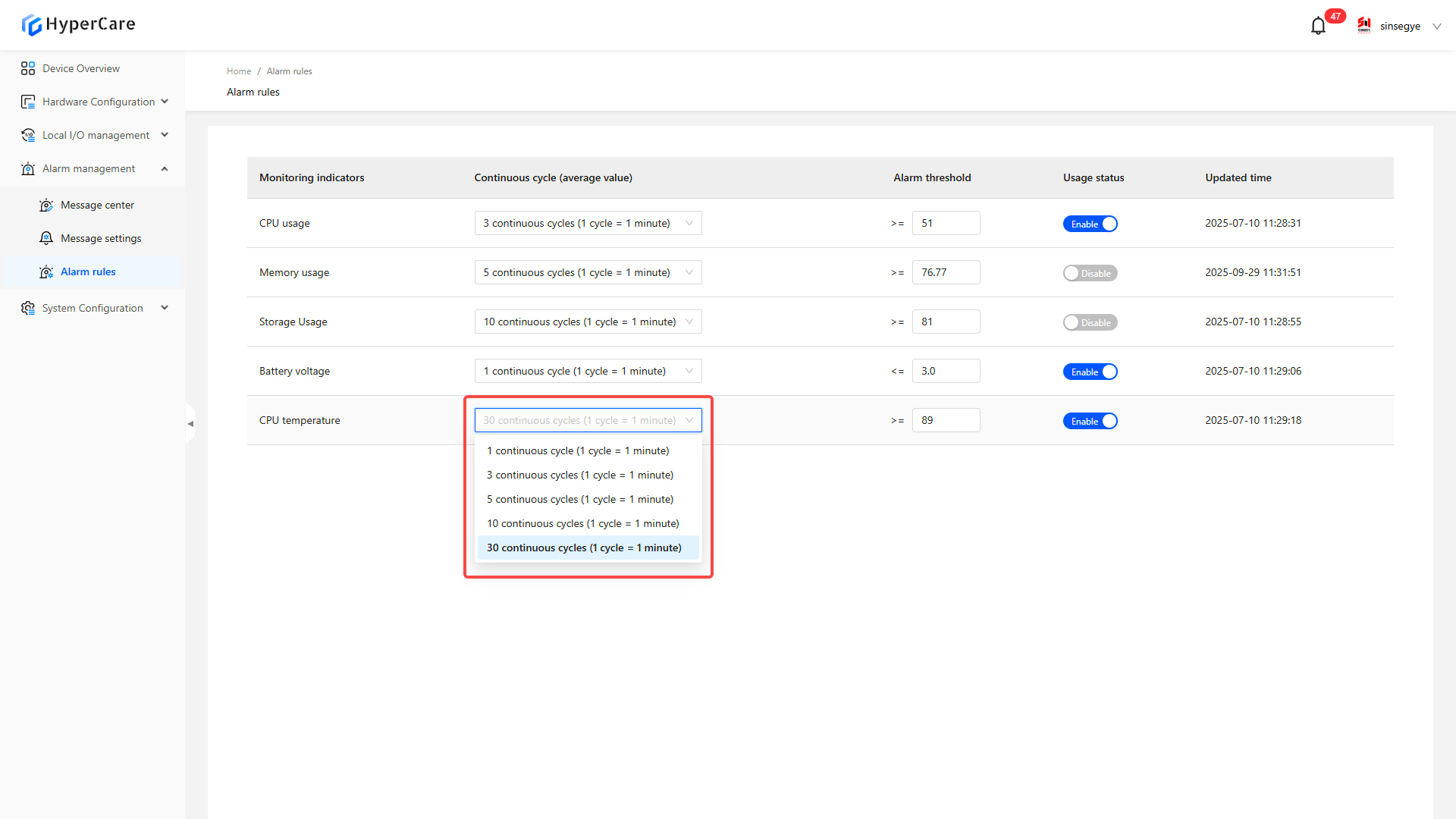
11.3.2 Set continuous cycles
Click the dropdown menu to select consecutive cycles (1 cycle = 1 minute)
11.3.3 Edit alarm thresholds
Click the numeric input box to modify:
| Metric type | Value range |
|---|---|
| CPU usage | 50%-100% |
| Memory usage | 50%-100% |
| Storage usage | 50%-100% |
| CMOS battery voltage | 2.2V-3.3V |
| CPU temperature | 50-100℃ |
 |
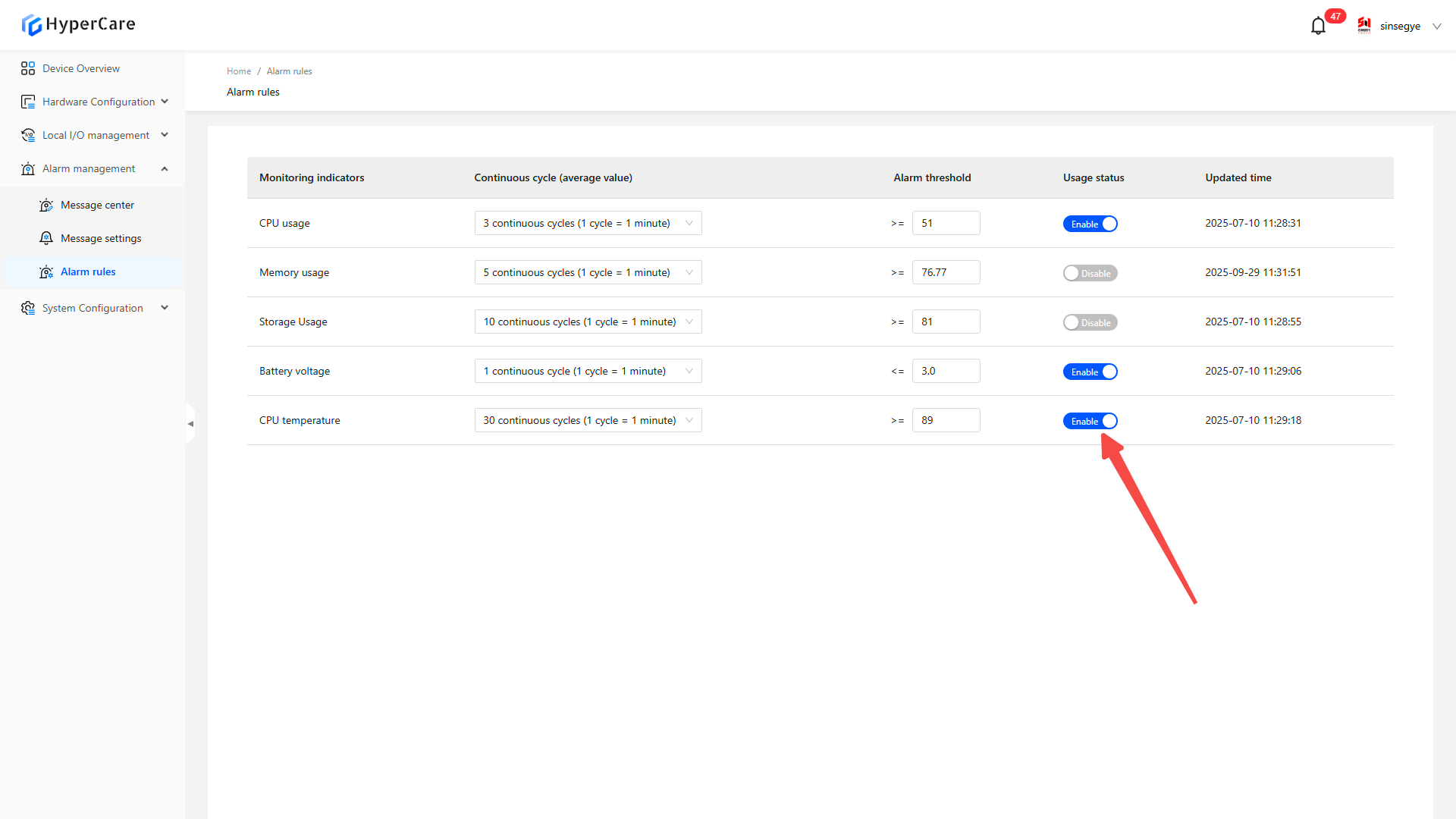
11.3.4 Enable/Disable Rules
Click the \[Enable/Disable] button to switch the enable/disable status:
12. System Configuration - Dual-Domain System
12.1 Scope of Application
It is applicable to all adapted models.
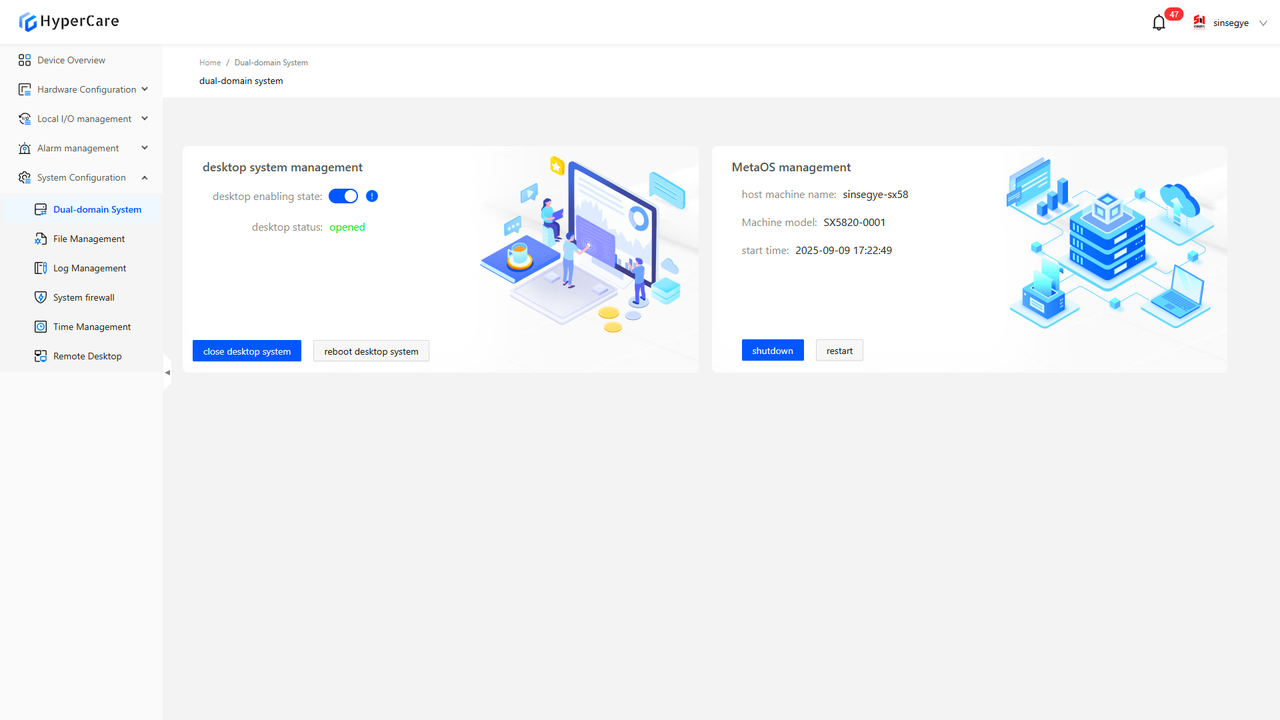
12.2 Function Introduction
This function is used to manage the power-on, shutdown, and restart operations of real-time domain and non-real-time domain (desktop) systems, as well as display relevant status and information.
12.3 Usage Details
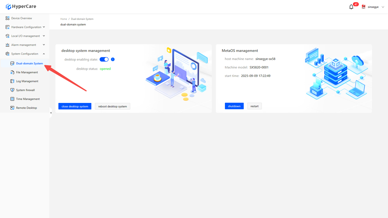
12.3.1 Enter the page
12.3.2 Shutdown of non-real-time domain
a. After clicking the \[Close Desktop System] button, a confirmation prompt will pop up.
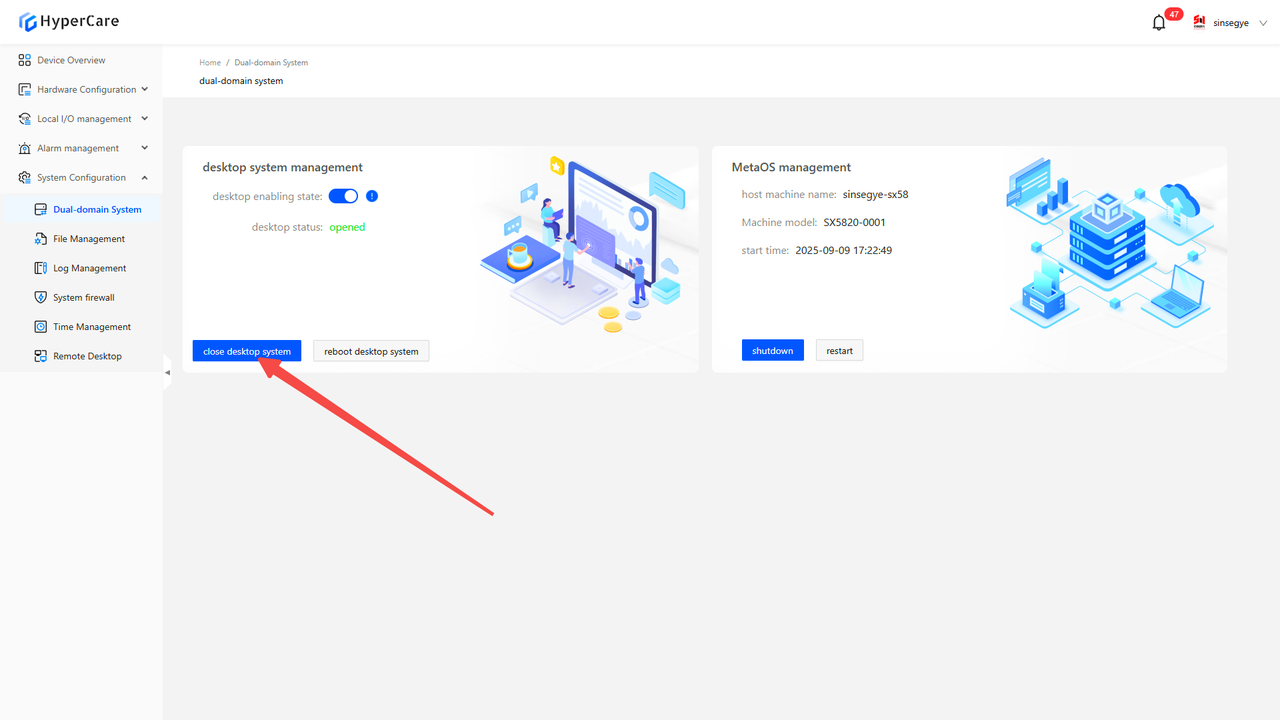
Clicking the \[Confirm Close] will close the non-real-time domain system (desktop) while keeping the real-time domain system running normally.

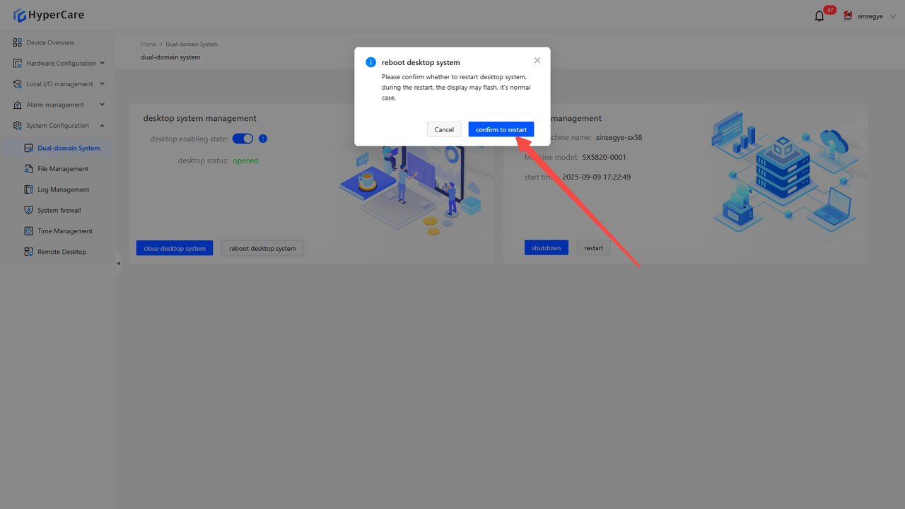
12.3.3 Restart of non-real-time domain
After clicking the \[Restart Desktop System] button, a confirmation prompt will pop up.
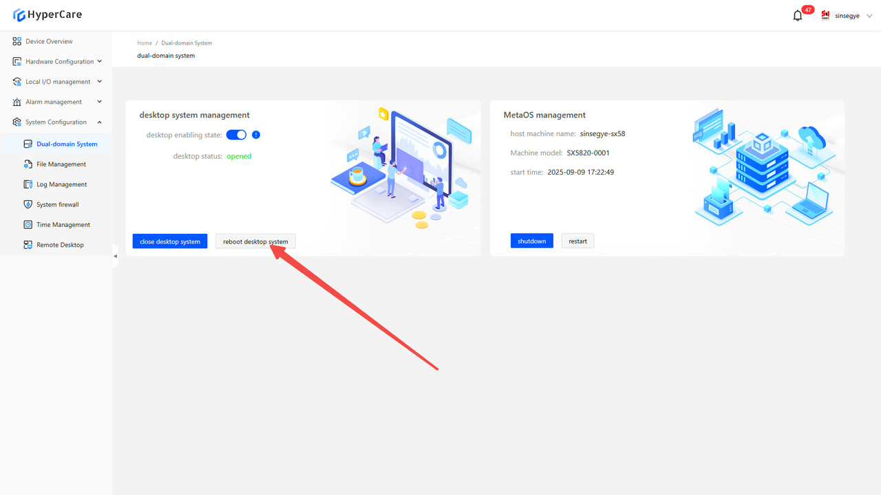
Clicking \[Confirm Restart] will restart the non-real-time domain system (desktop) while keeping the real-time domain system running normally.
| The \[Close Desktop System] operation does not preserve the state - if the iComputer is restarted, the non-real-time domain (desktop) will restart automatically. |
|---|
12.3.4 Enable non-real-time domain
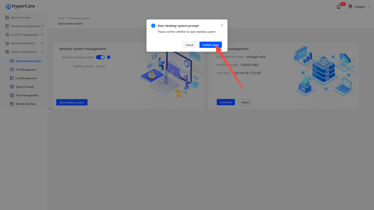
After clicking the \[Enable Desktop System] button, a confirmation prompt will pop up.
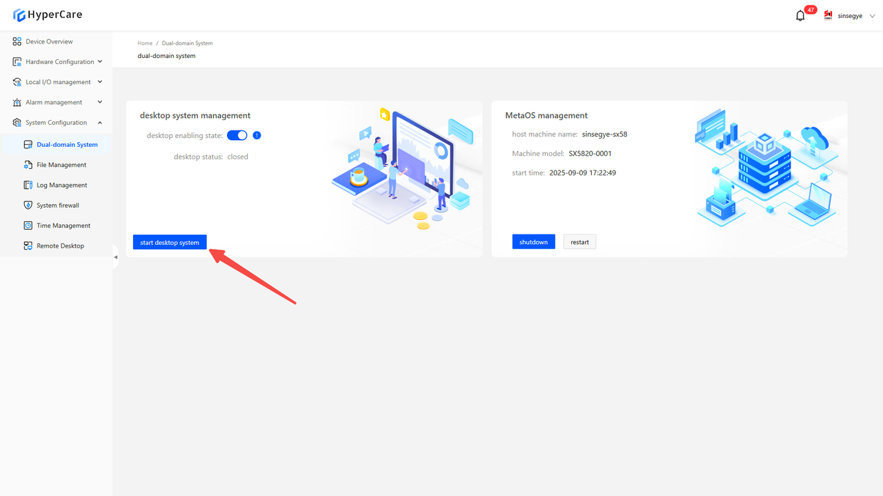
Clicking the \[Confirm ON] button will start the closed non-real-time domain system (desktop) while keeping the real-time domain system running normally.
12.3.5 Disable non-real-time domain
After clicking the \[Desktop Enable Status] switch to perform the \[OFF] operation, a confirmation prompt will pop up.
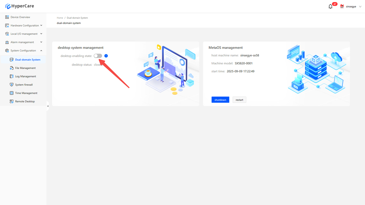
Clicking \[Confirm OFF] will permanently disable the non-real-time domain system (desktop) until “enable” is turned on.
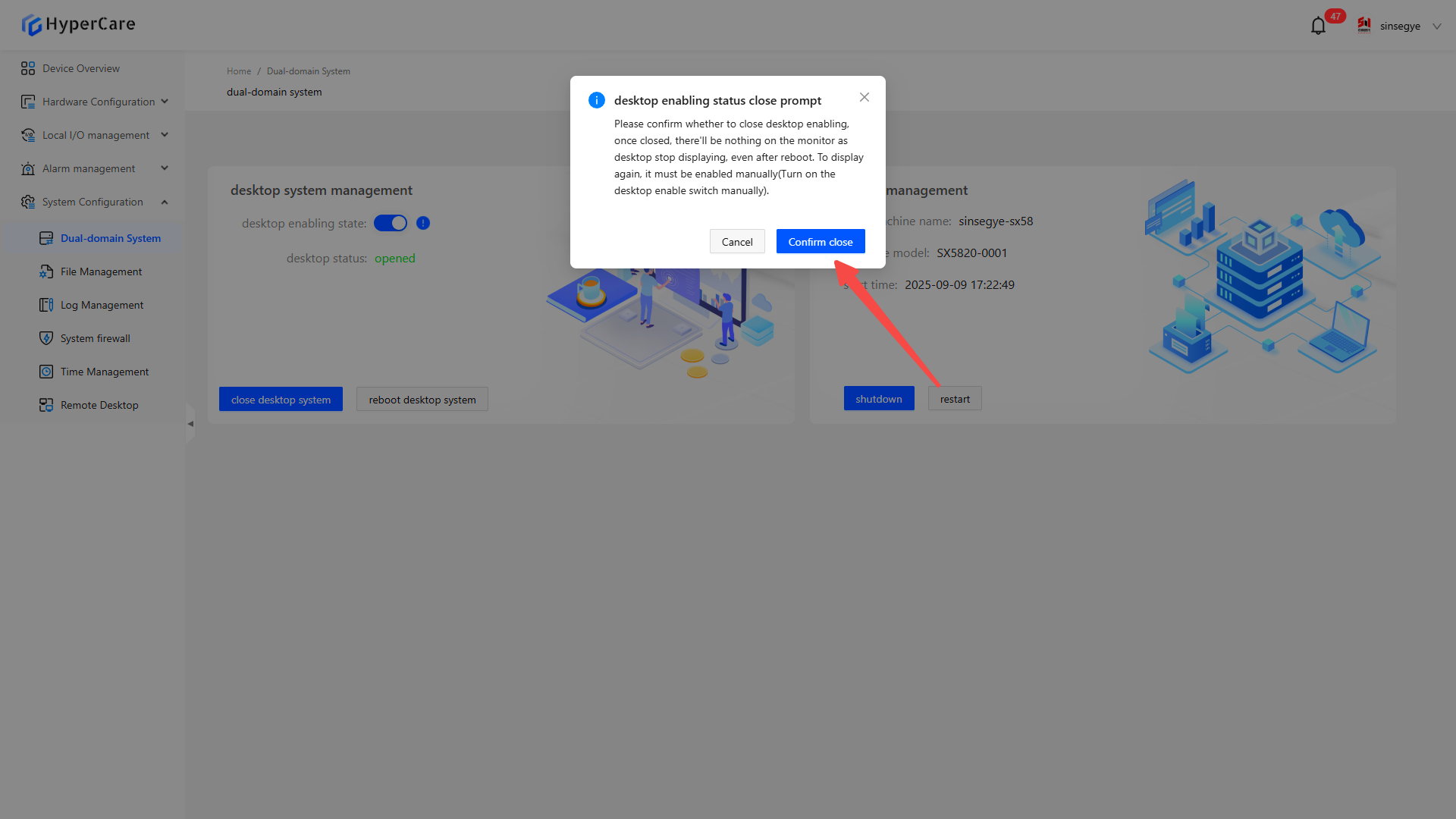
| After the \[Desktop Enable] status is retained as \[OFF], if the iComputer is restarted, the non-real-time domain (desktop) will remain disabled and will not start automatically. |
|---|
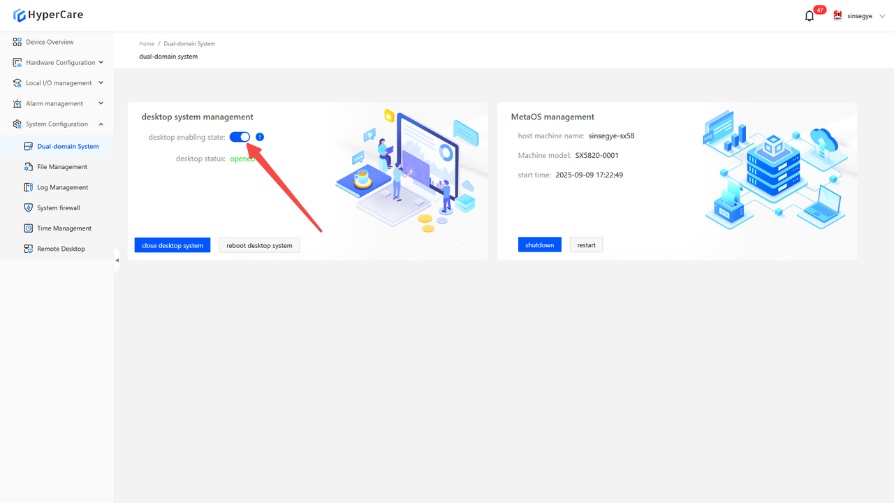
12.3.6 Enable non-real-time domain
After clicking the \[Desktop Enable] slider to perform the \[ON] operation, a confirmation prompt will pop up.
Clicking the \[Confirm ON] button will start the non-real-time domain system (desktop) and support power-on, shutdown, and restart operations.
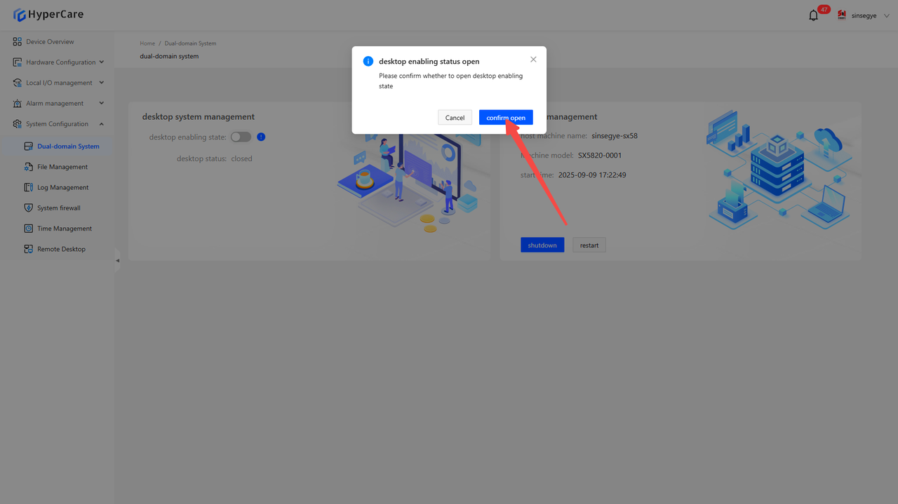
| When the \[Desktop Enable] status remains \[ON], if the iComputer is restarted, the non-real-time domain system (desktop) will start normally and support power-on, shutdown, and restart operations. |
|---|
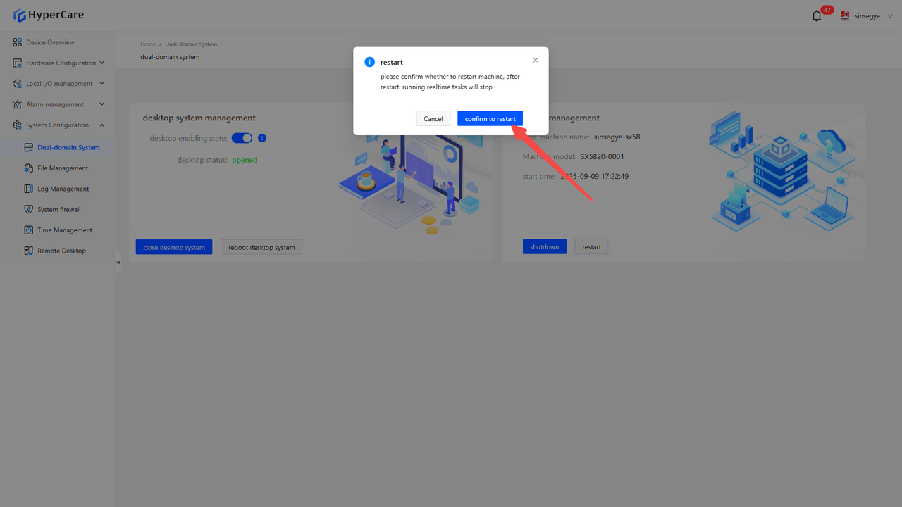
12.3.7 Restart of real-time domain
After clicking the \[Restart] button, a confirmation prompt will pop up.
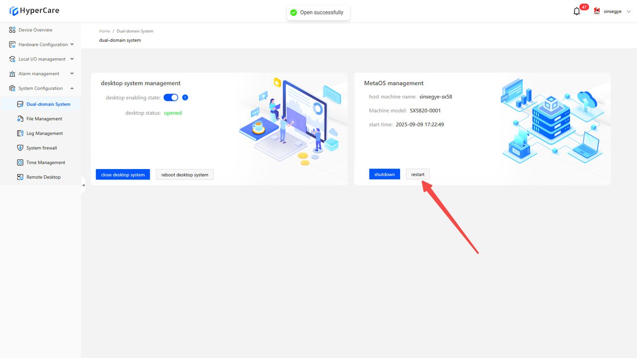
Clicking the \[Confirm Restart] button will restart the entire iComputer.
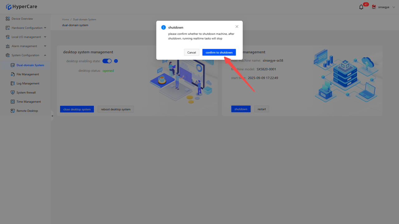
12.3.8 Shutdown of real-time domain
After clicking the \[Shutdown] button, a confirmation prompt will pop up.
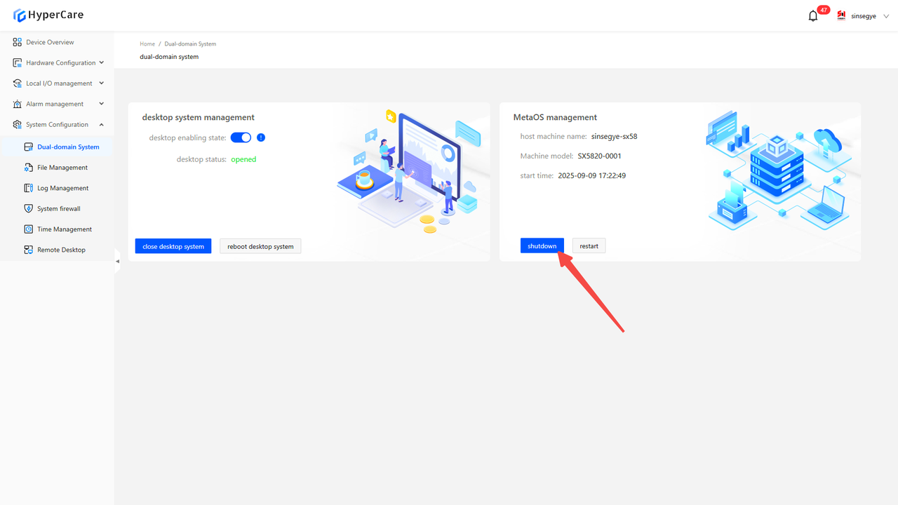
Clicking \[Confirm Shutdown] will power off the entire iComputer.
12.3.9 Important notes
-
Do not click on \[Network Port Configuration], \[PCIE Configuration], or \[Memory Configuration] tabs during the switching process of the non-real-time domain system.
-
After the entire iComputer is restarted, the webpage will lose connection. After the iComputer fully starts, you need to manually refresh the webpage to resume normal operation.
-
After clicking the button, patiently wait for the webpage to automatically refresh the desktop status, and avoid repeatedly clicking the button multiple times.
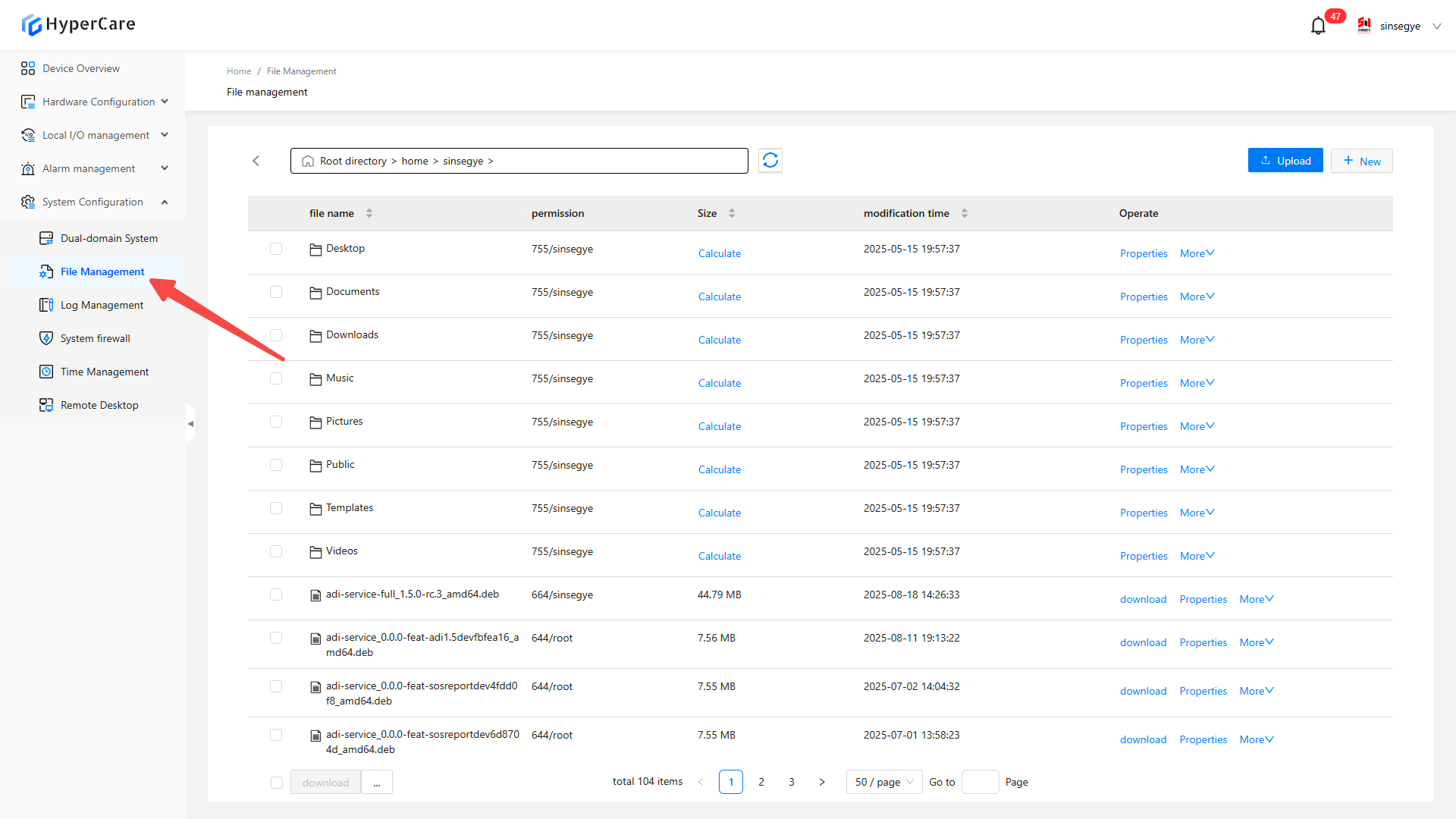
13. System Configuration - File Management
13.1 Scope of Application
It is applicable to all adapted models.
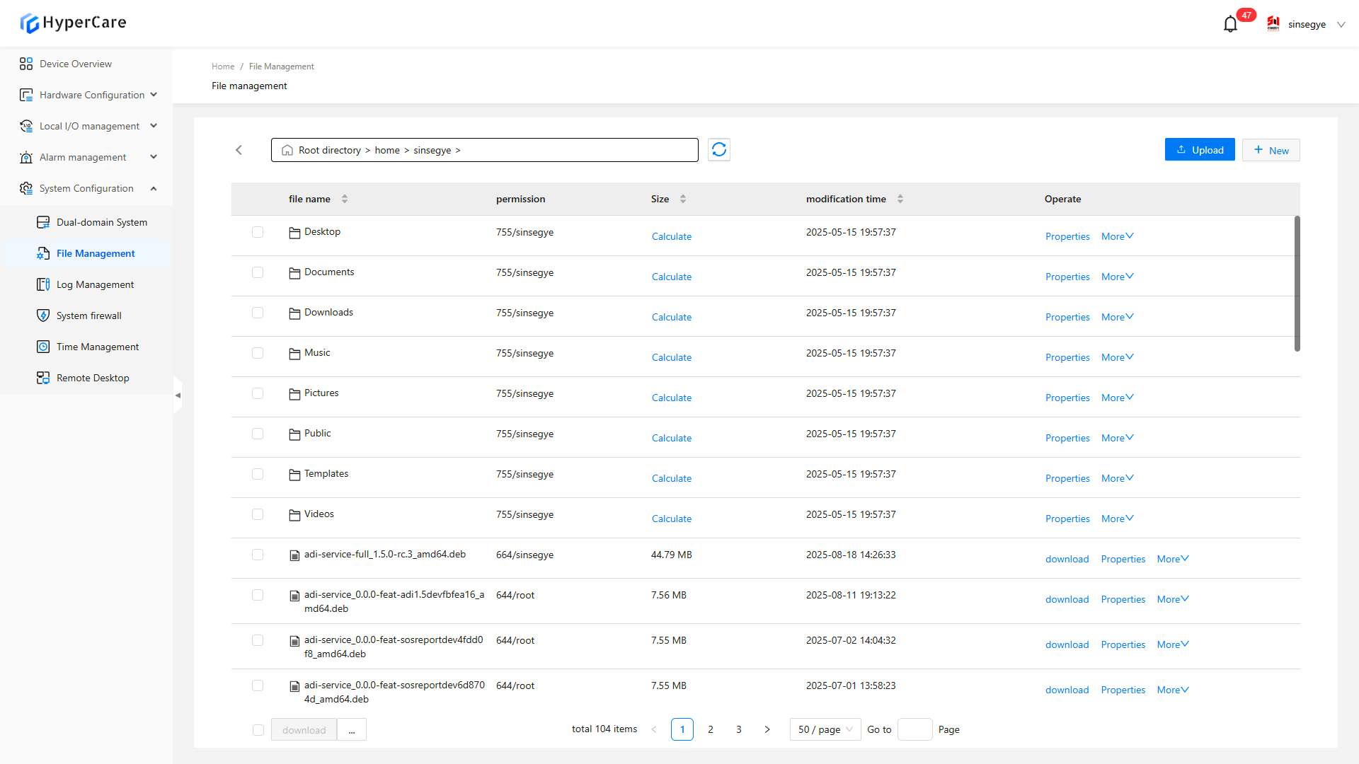
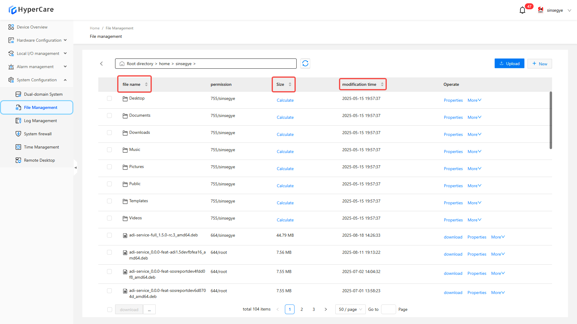
13.2 Function Introduction
It provides real-time domain system file management functions, and supports directory browsing, file operations (upload/download/edit/compress), permission management, batch processing, and other operations.
13.3 Usage Details
13.3.1 Enter the page
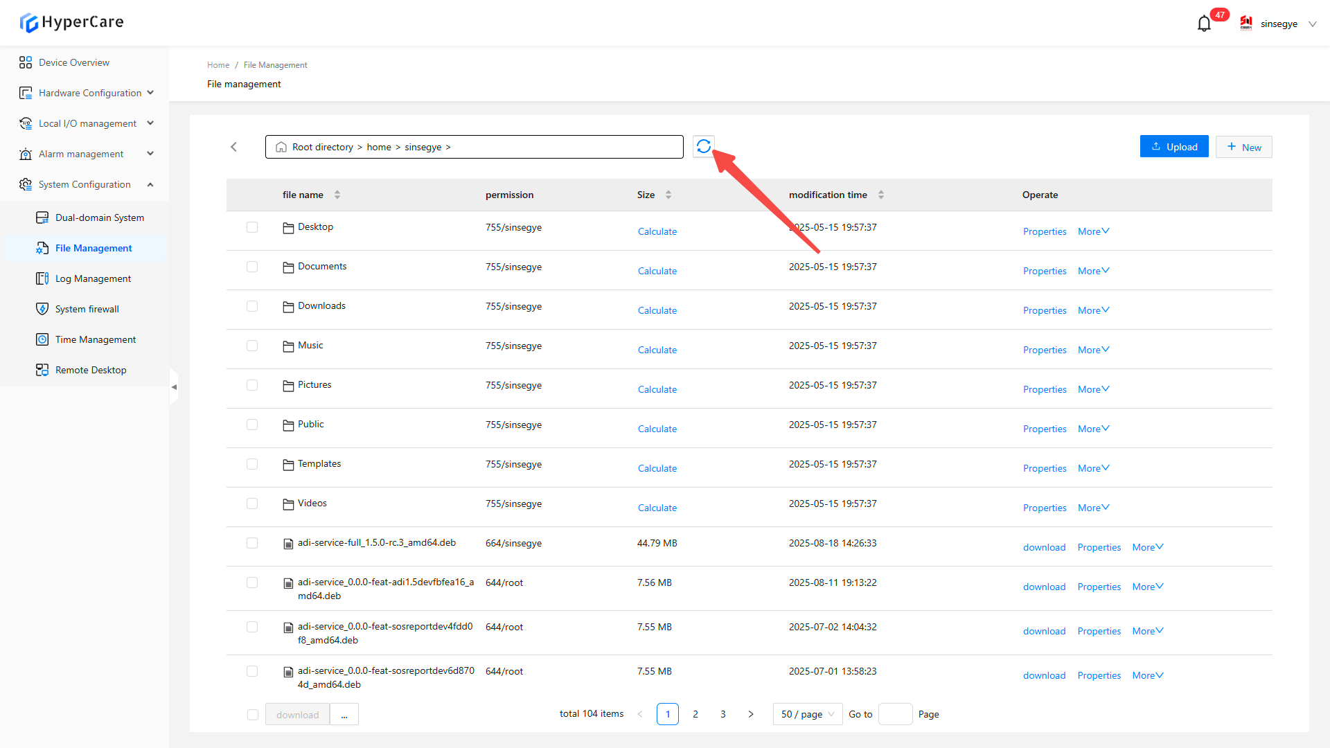
13.3.2 Refresh
Refresh the current directory contents
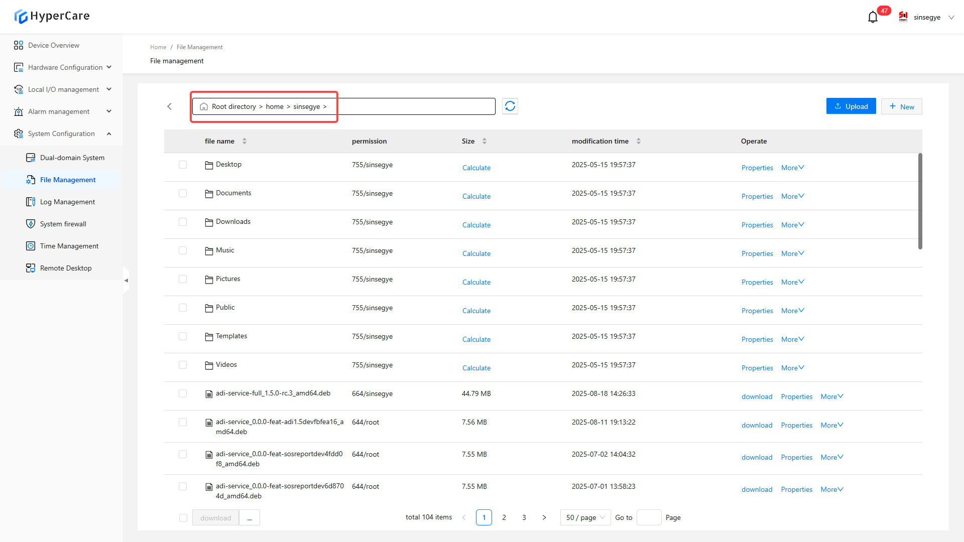
13.3.3 Path switching
Manually enter the path and press \[Enter] to jump to the specified directory.
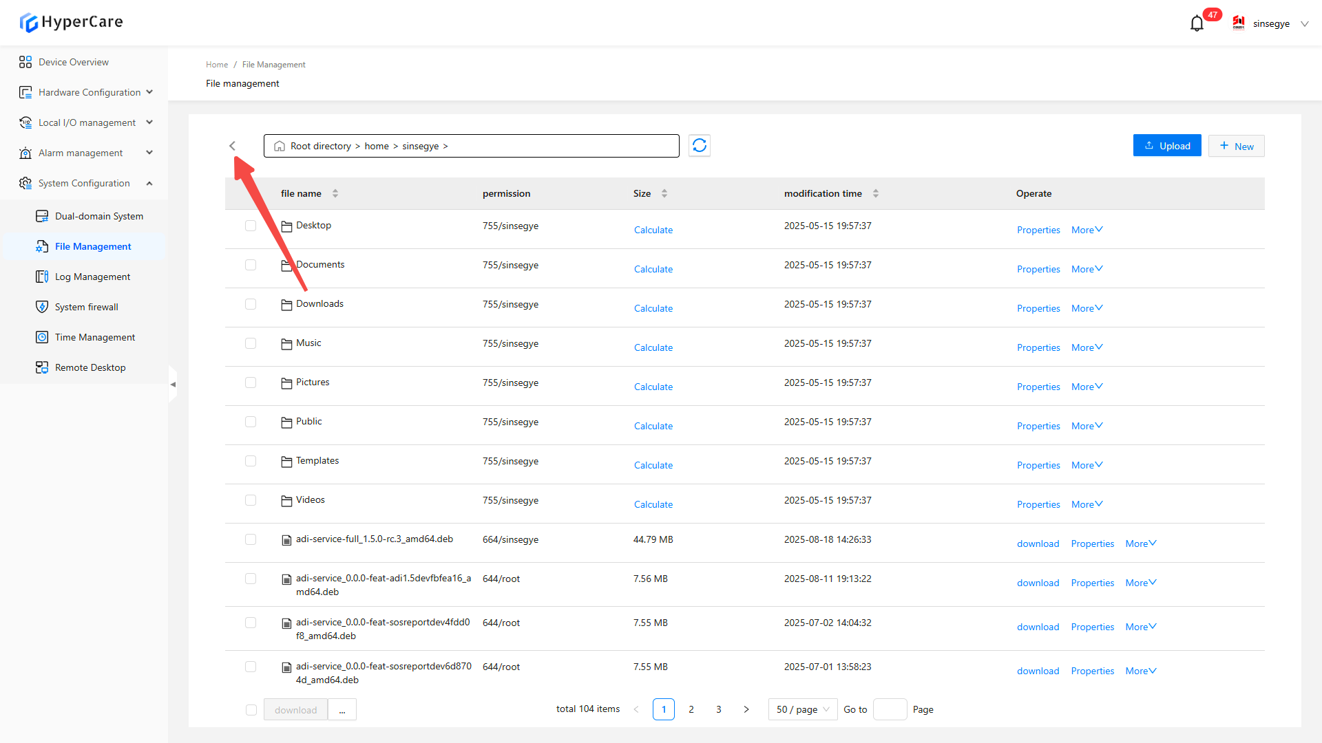
Click the \[<] button to jump to the parent directory.
13.3.4 Upload
Click the \[Upload] button
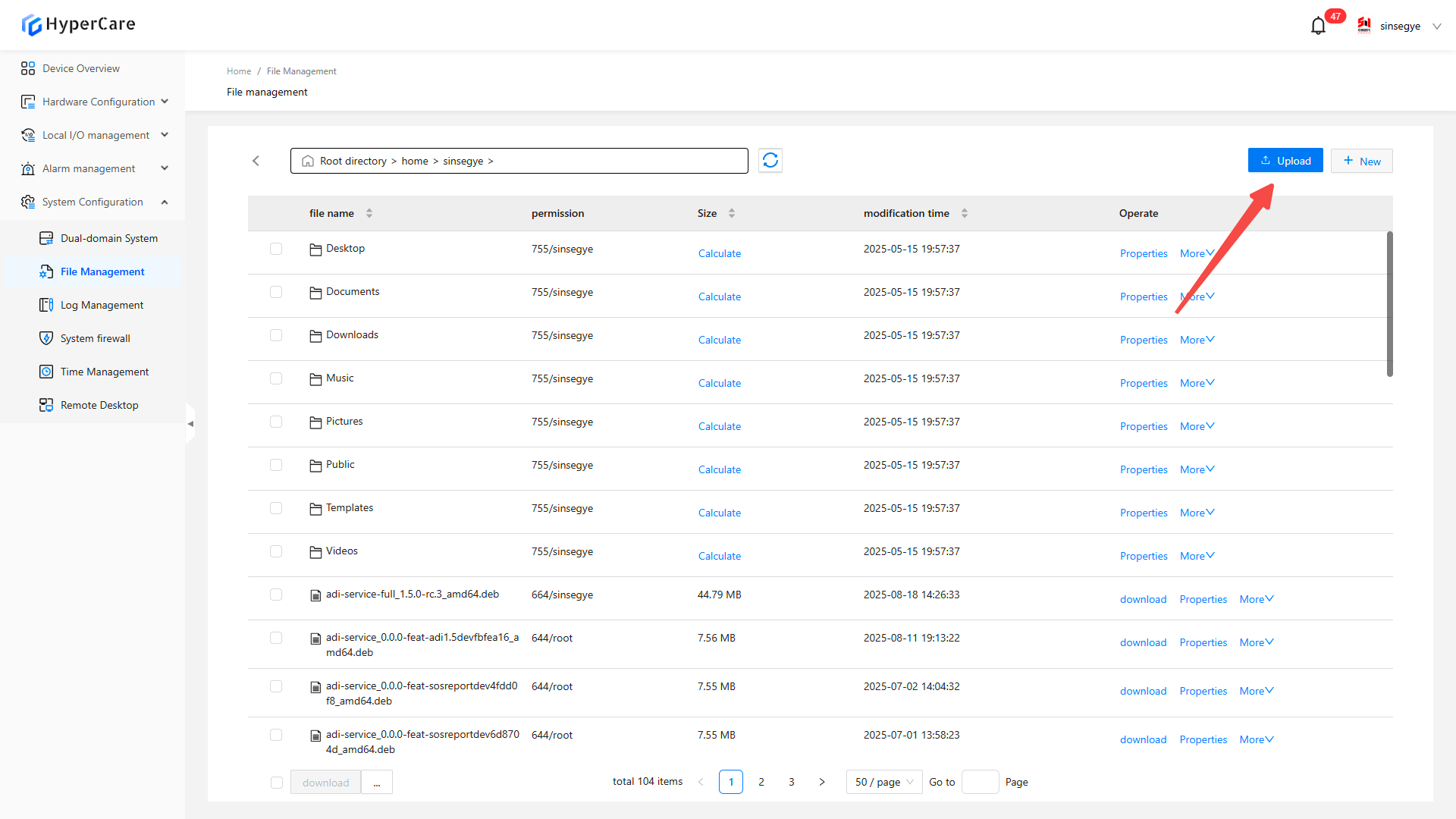
Select \[File] or \[Folder]
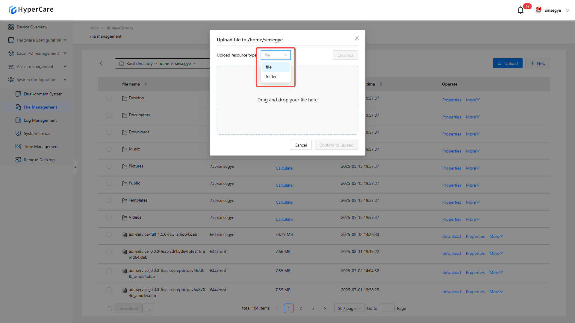
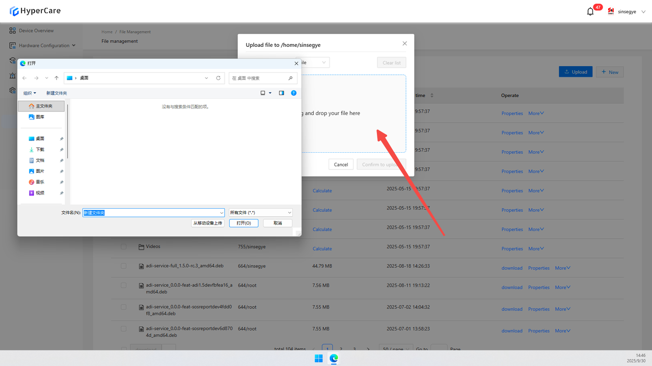
- Drag files/folders to the interface to trigger upload
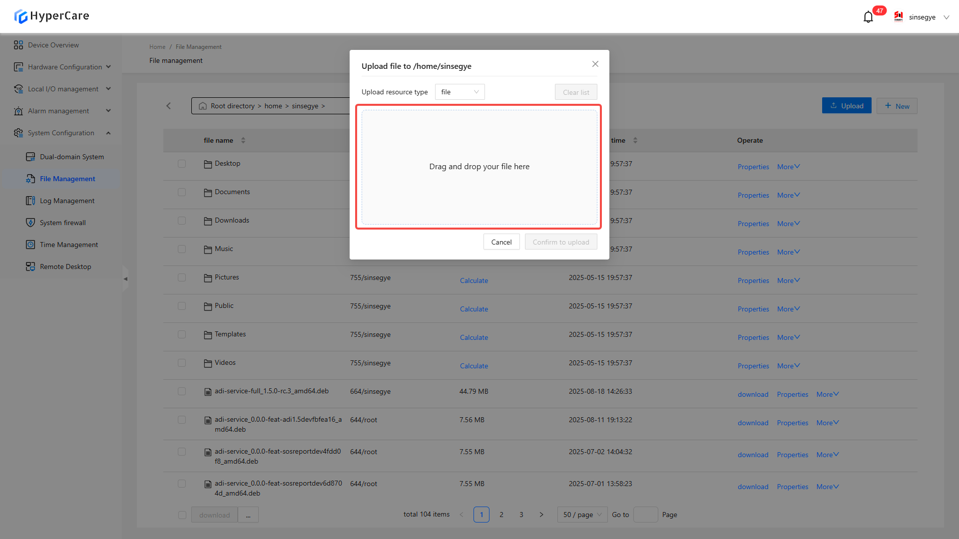
Or click the selected file to upload
13.3.5 Create
Click \[New]
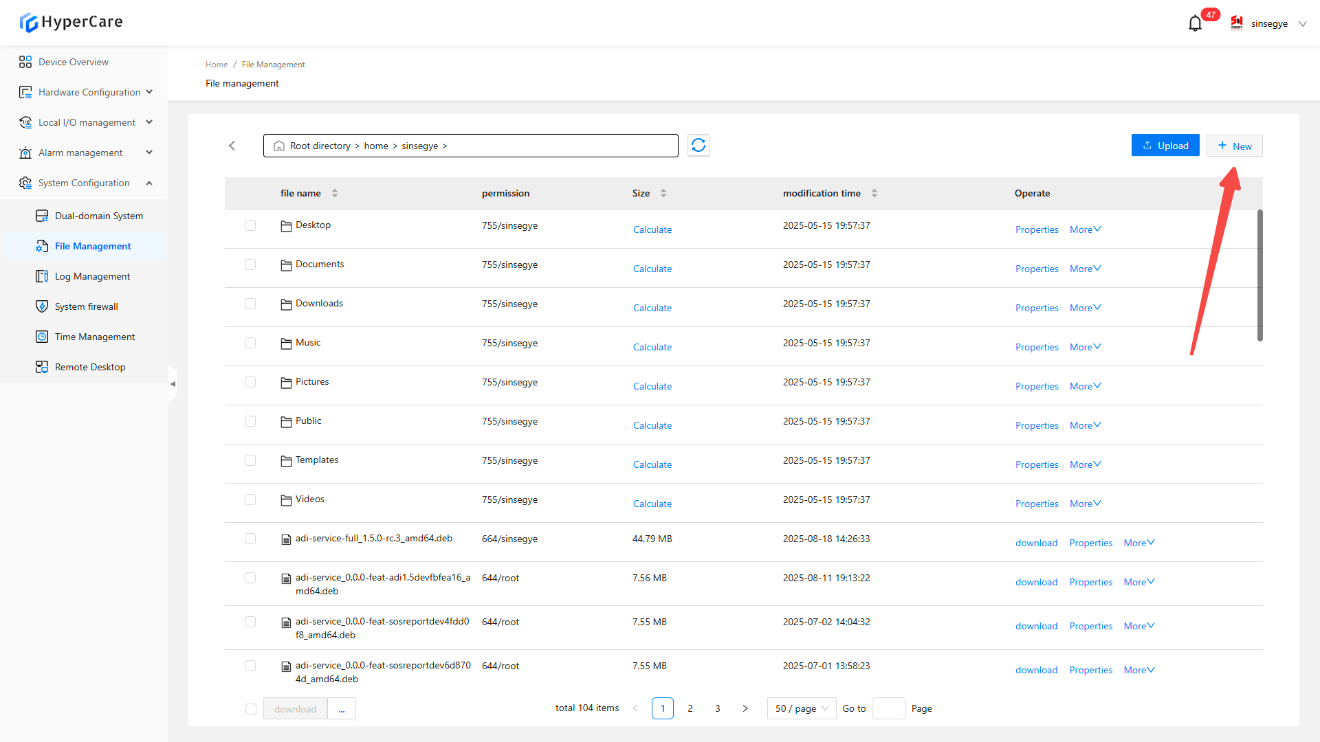
Select \[New File] or \[New Folder]
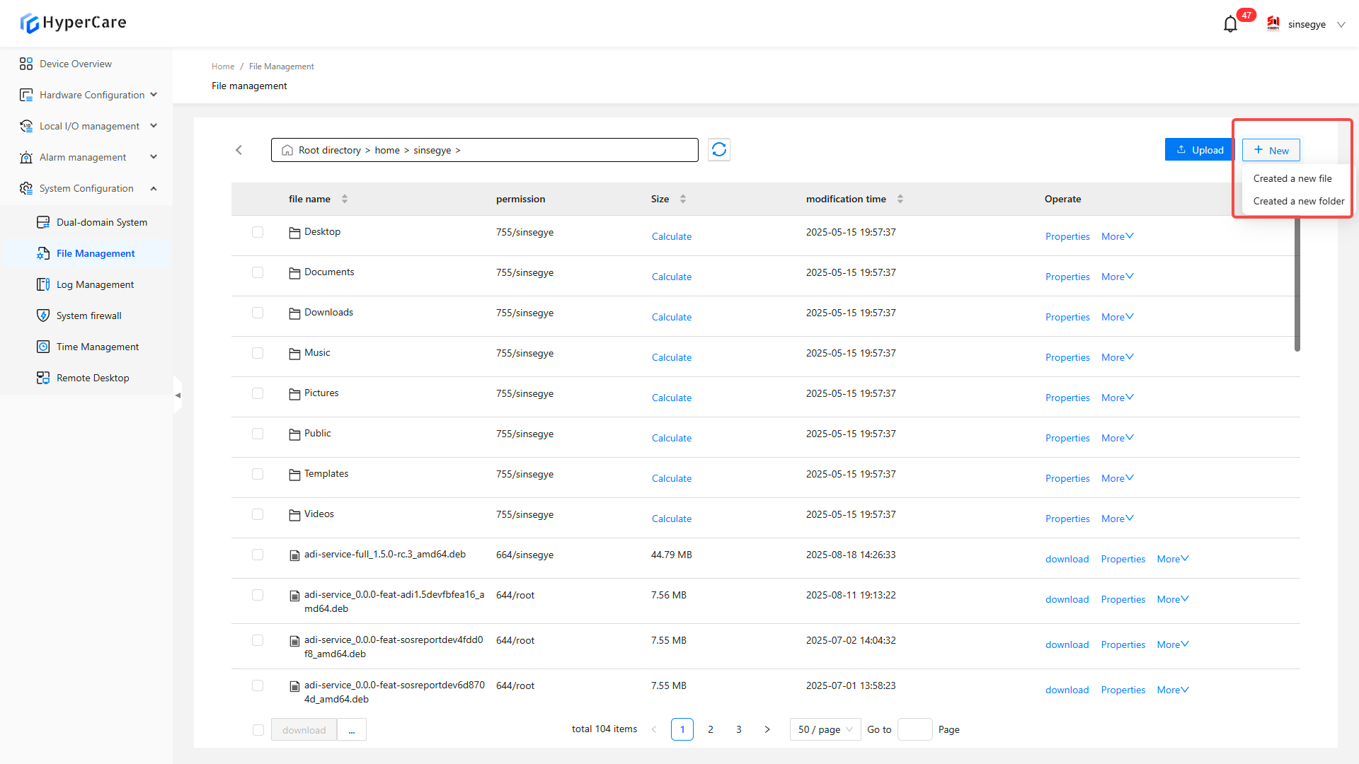
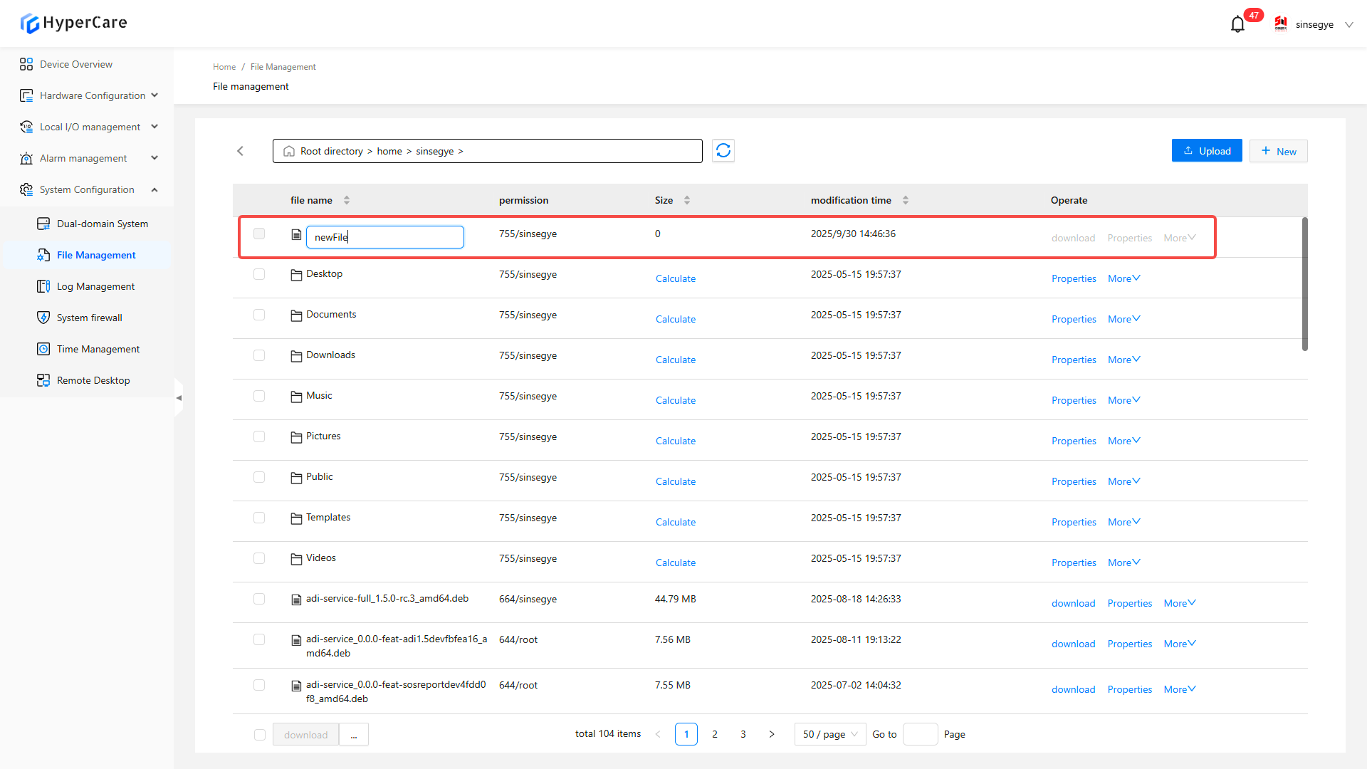
Automatically insert an entry at the top of the list, and the file name will be in the editing mode. Enter name and then press \[Enter] to save
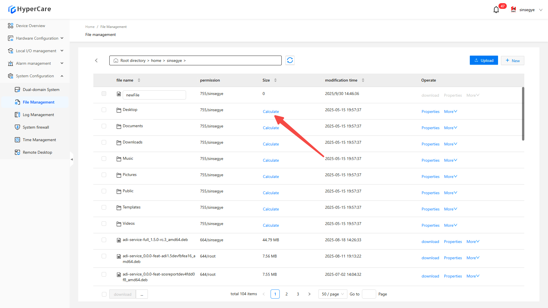
13.3.6 Calculate the file size
Click \[Calculate] to display the file size
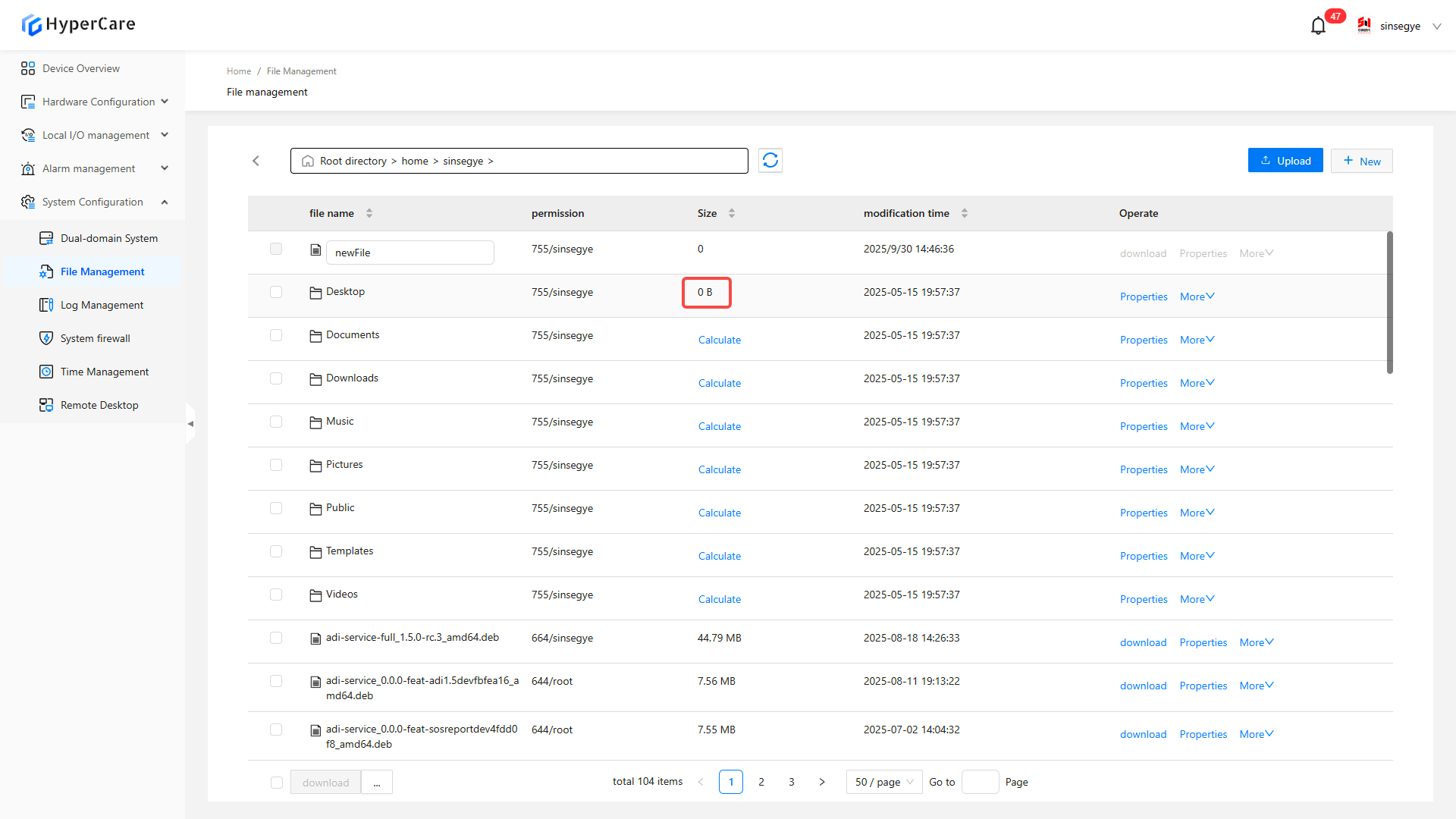
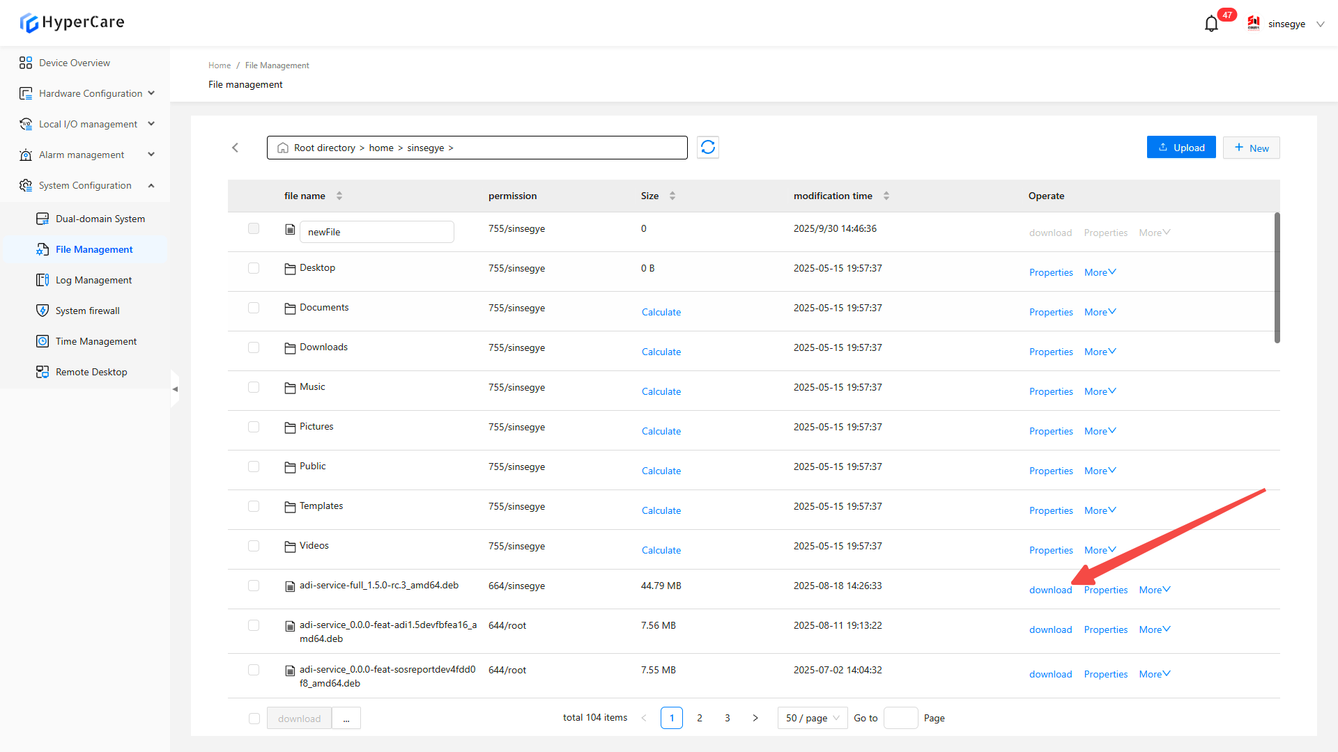
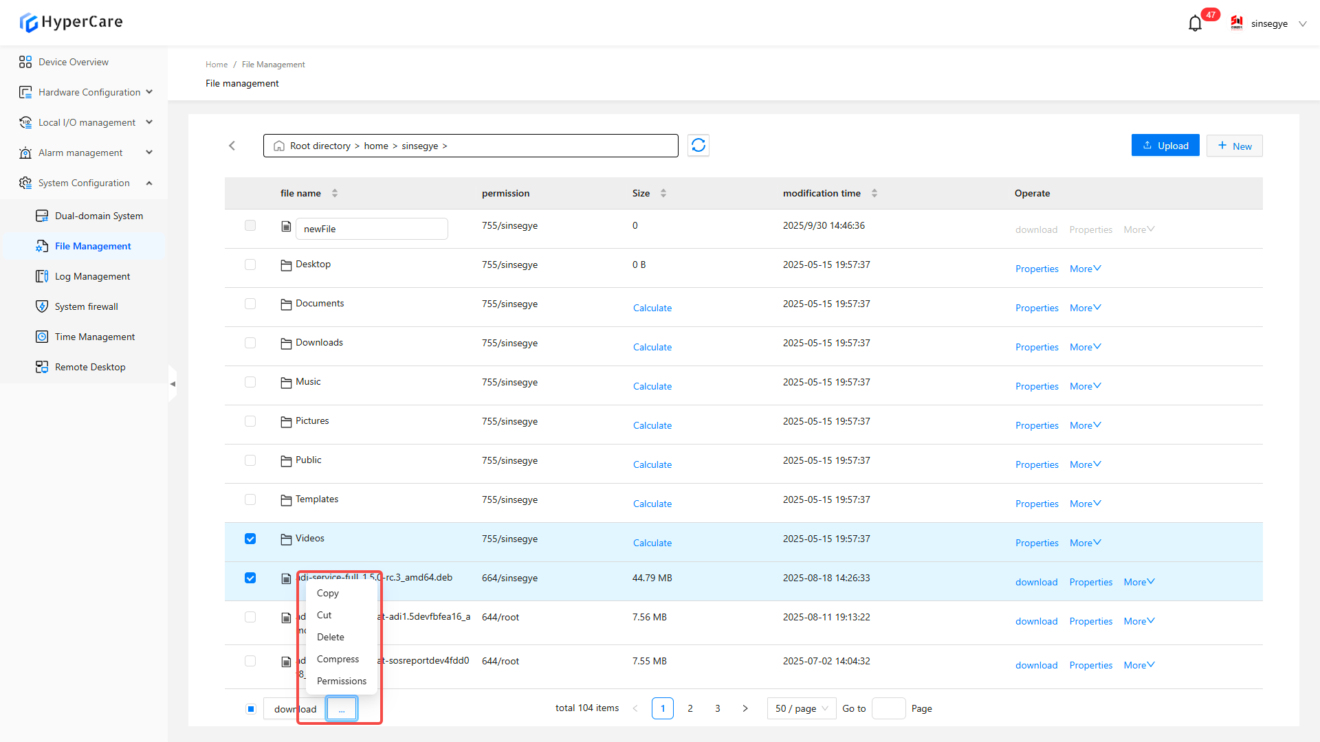
13.3.7 File operatio
Download: Save it to the local download directory
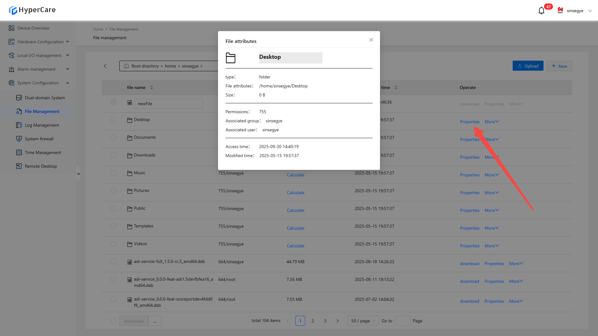
Property: Display details such as file type, full path (replicable), size, promission, time stamp
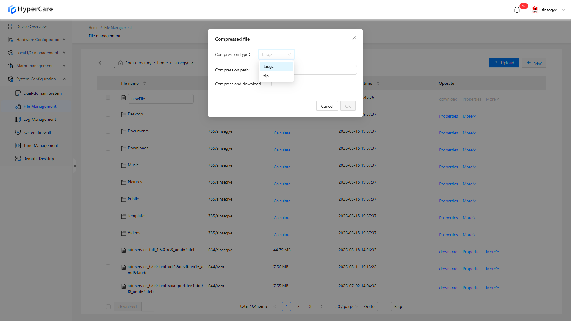
Compression: Supported formats: tar.gz/zip
Optional operations: Compress to a specified path or download directly after compression
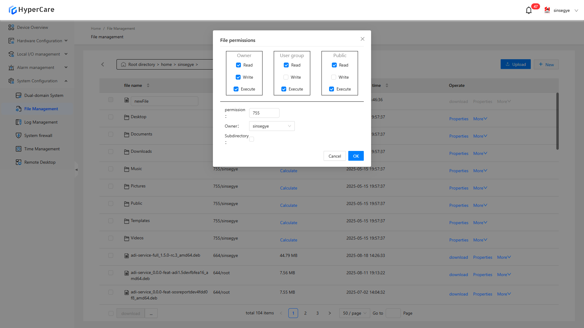
- Permission:
-
You can select permissions for owner, group, and public. After that, the numeric value at “Permissions” will be automatically updated below
-
You can also edit the numeric value in "Permissions" below to sync with the checkboxes above
-
Read 4, Write 2, Execute 1
-
For the numeric value of "Permission", each digit has a maximum value of 7 and a fixed length of 3 digits, and each digit can potentially be 0
-
Owner: Dropdown selection. All users within the current operating system are available
-
Subdirectory: If checked, it means that the same permissions has been applied to the current folder and its subfolders/files
13.3.8 Batch operation
Check \[Select All] at the left corner or check a file to display the operation bar.
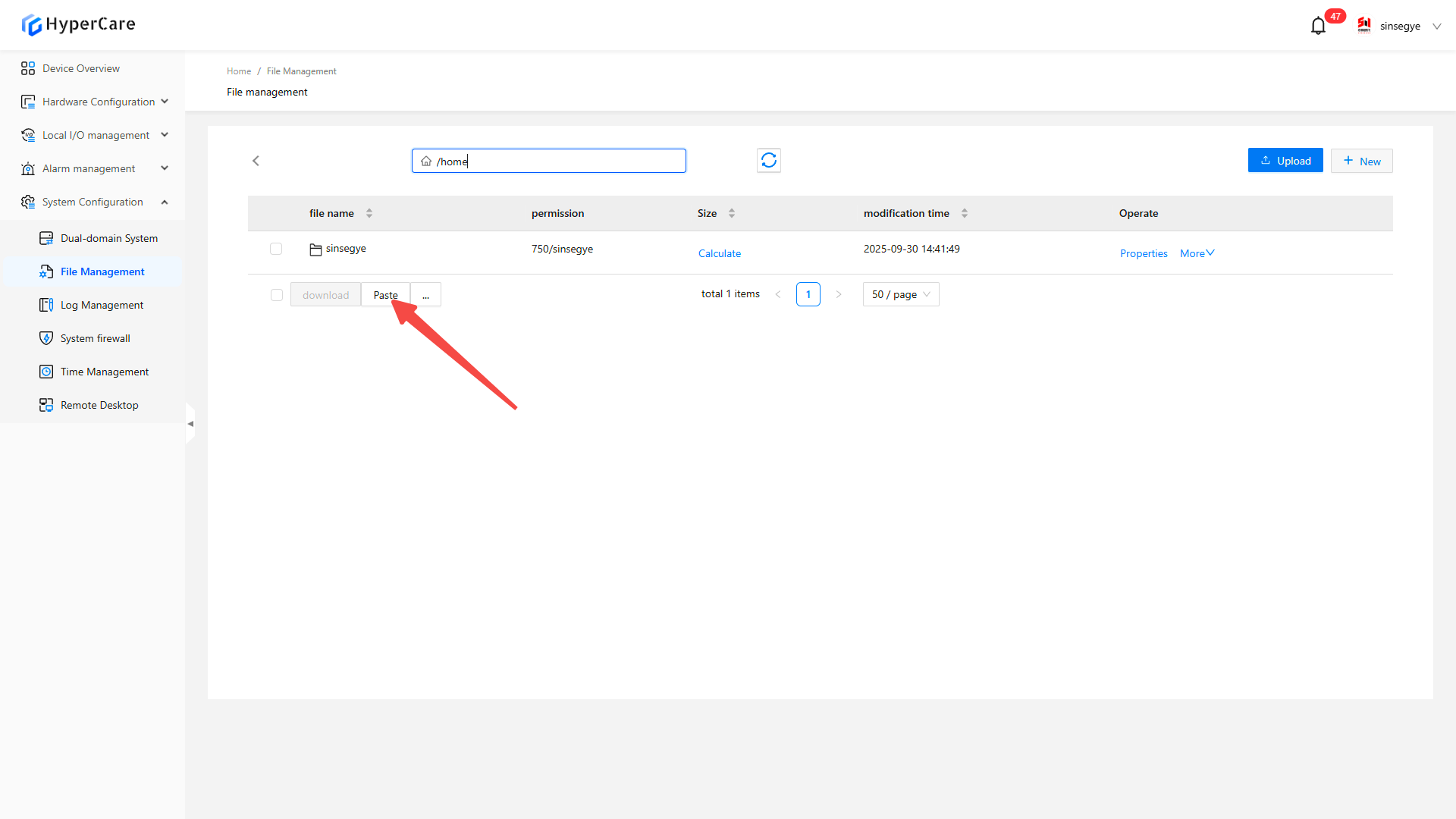
13.3.9 Paste
After performing the “Copy/Cut” operation, the \[Paste] button will displayed in the left corner
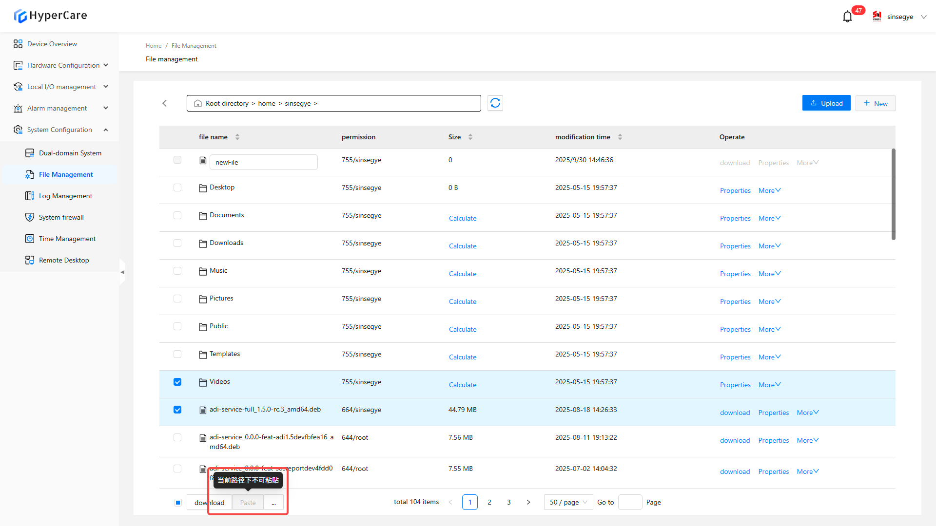
After switching the target, click \[Paste] to complete the operation
13.3.10 Sorting
Support sorting by \[File Name], \[Size] and \[Modification Time]. Click \[Sorting Arrow] to sort.
14. System Configuration - Log Management
14.1 Scope of Application
It is applicable to all adapted models.
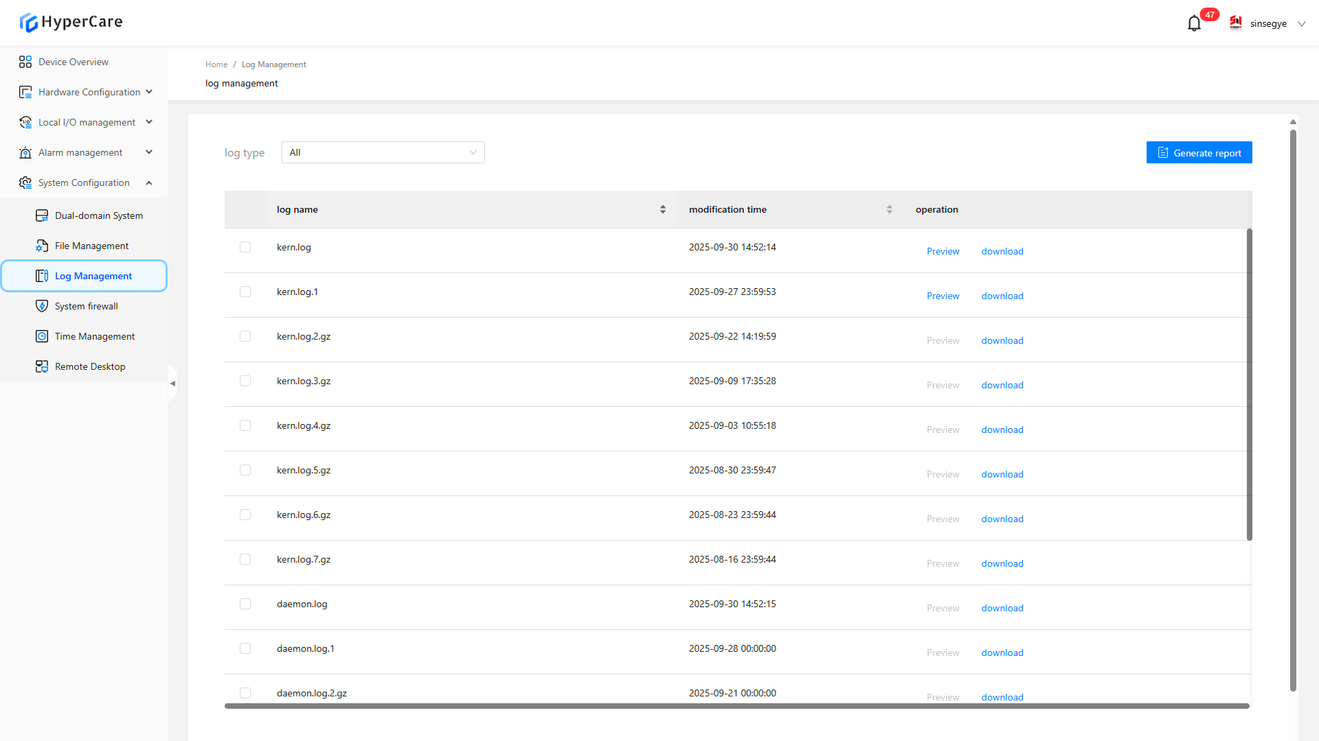
14.2 Function Introduction
This function is used to view and download relevant log files in the real-time domain system.
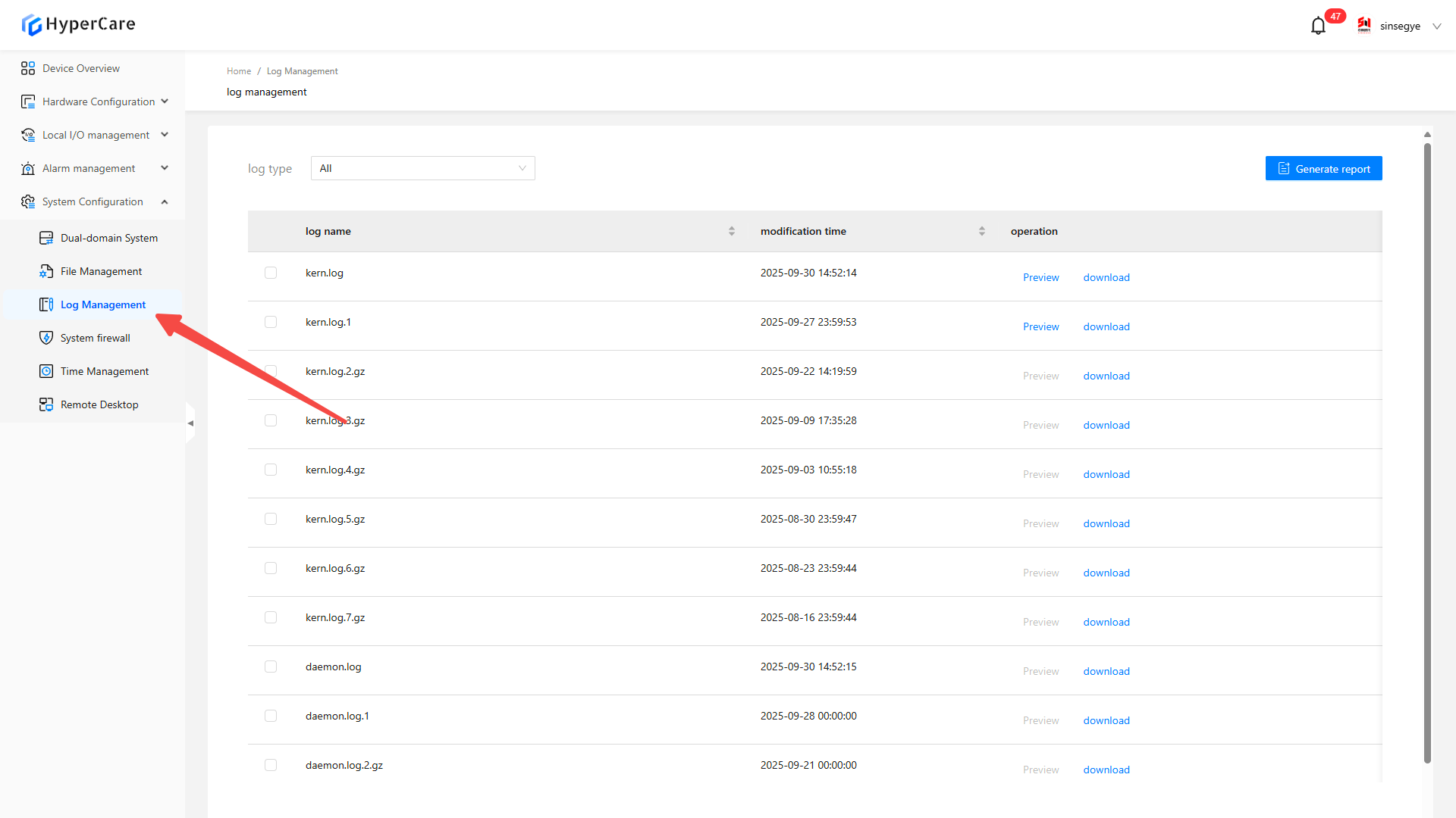
14.3 Usage Details
14.3.1 Enter the page
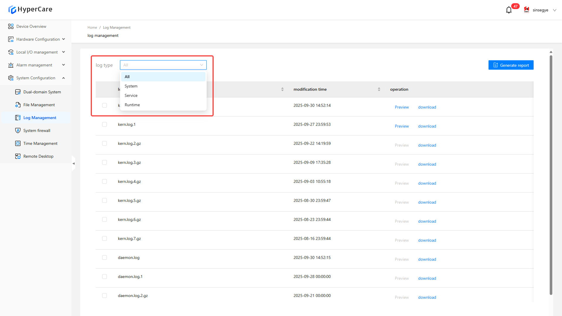
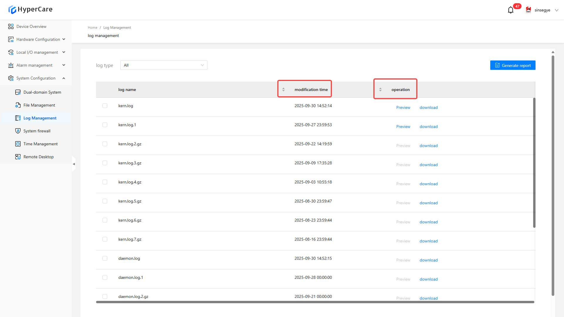
14.3.2 Log classification
-
\[All]: Display all log files.
-
\[System]: Display kernel logs.
-
\[Service]: Display daemon logs.
-
\[Runtime]: Display RTE logs.
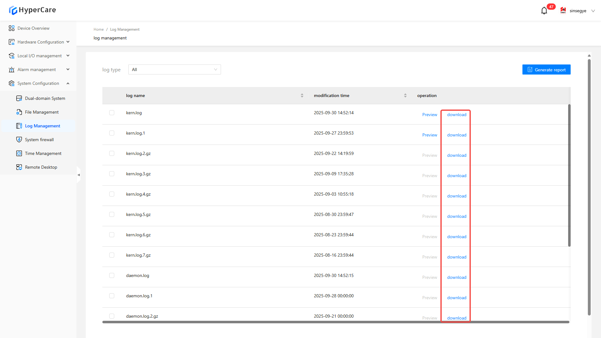
14.3.3 Single file download
To download a single file, select the desired file and then click the corresponding \[Download] button.
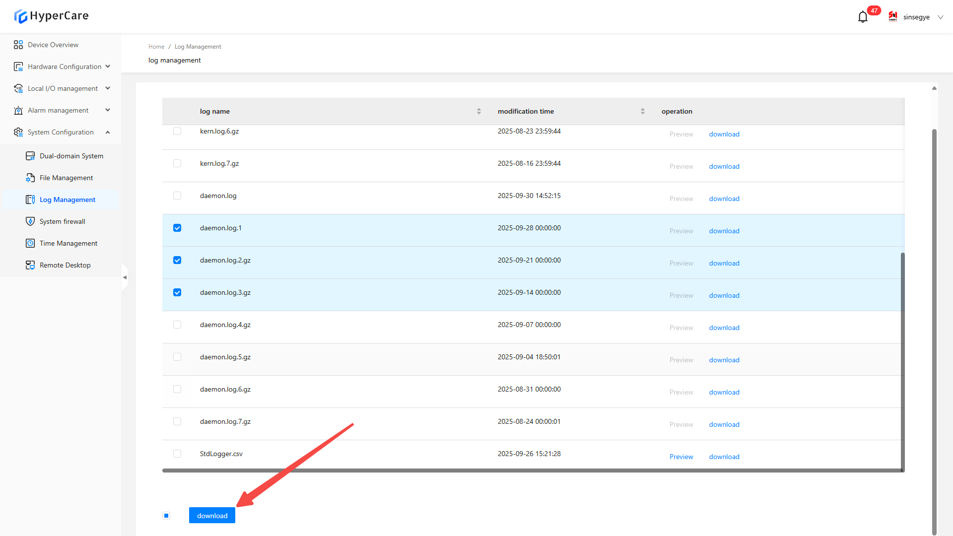
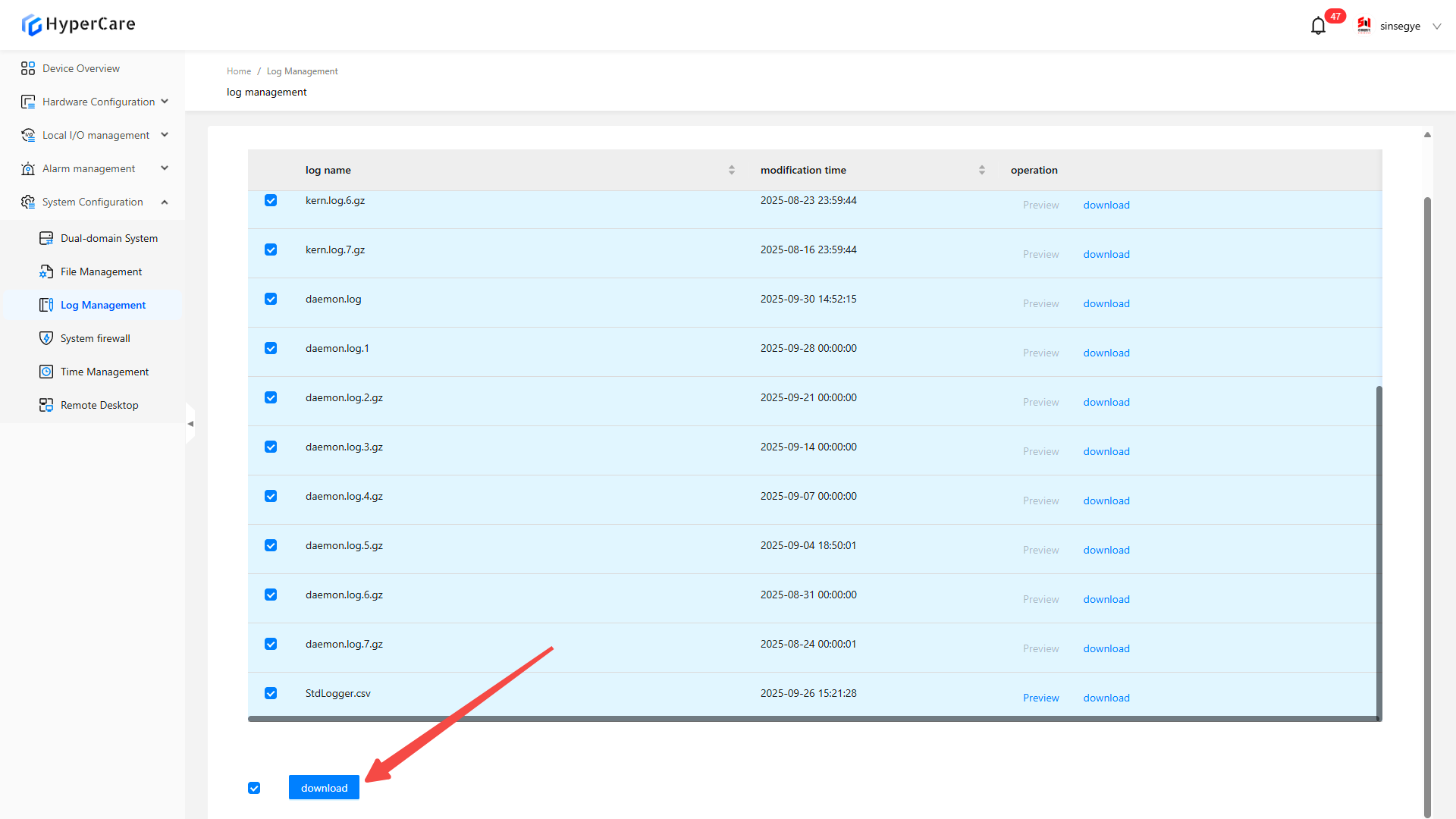
14.3.4 Batch download
To download multiple files simultaneously, select multiple files by checking the checkboxes in front of them.
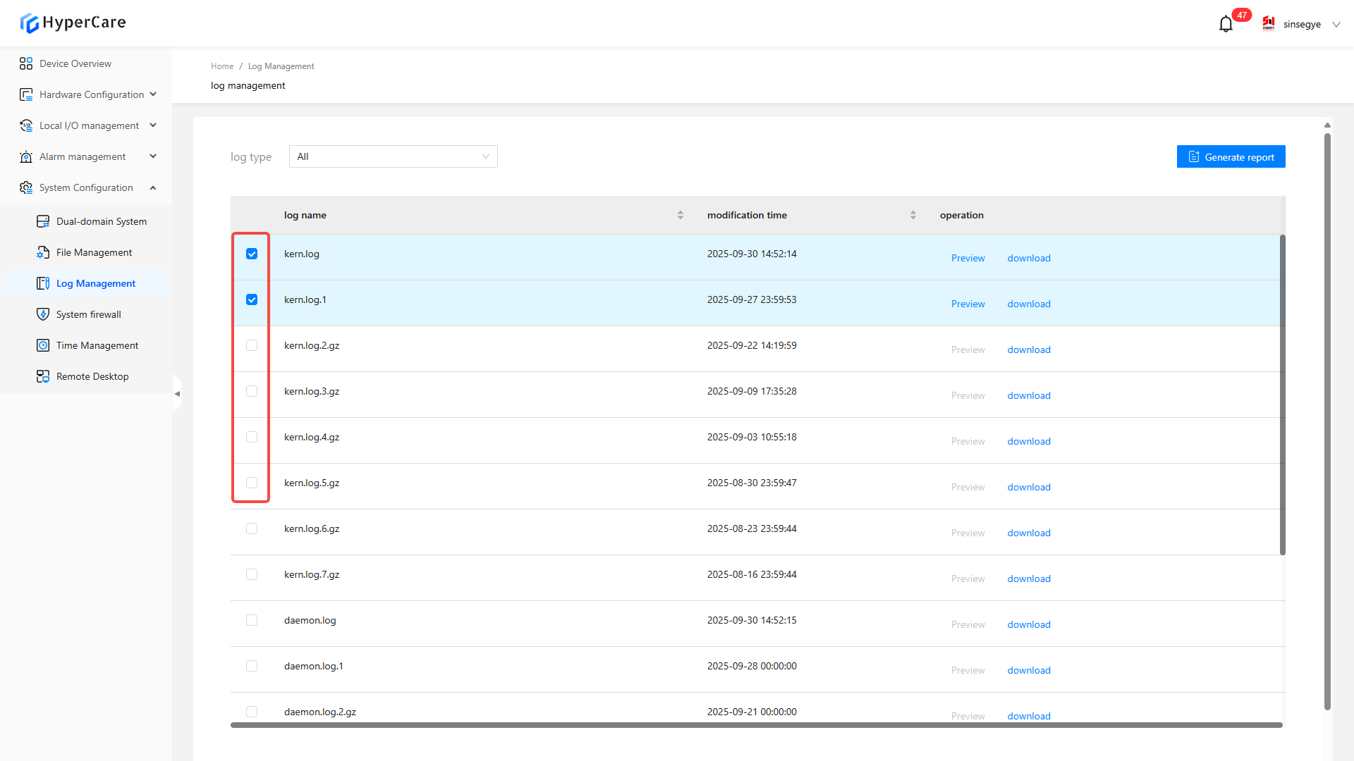
Click the \[Download] button at the bottom for batch download.
14.3.5 Download all files
To download all files at once, select all files by checking the \[All] in the left of of the \[Download] button.
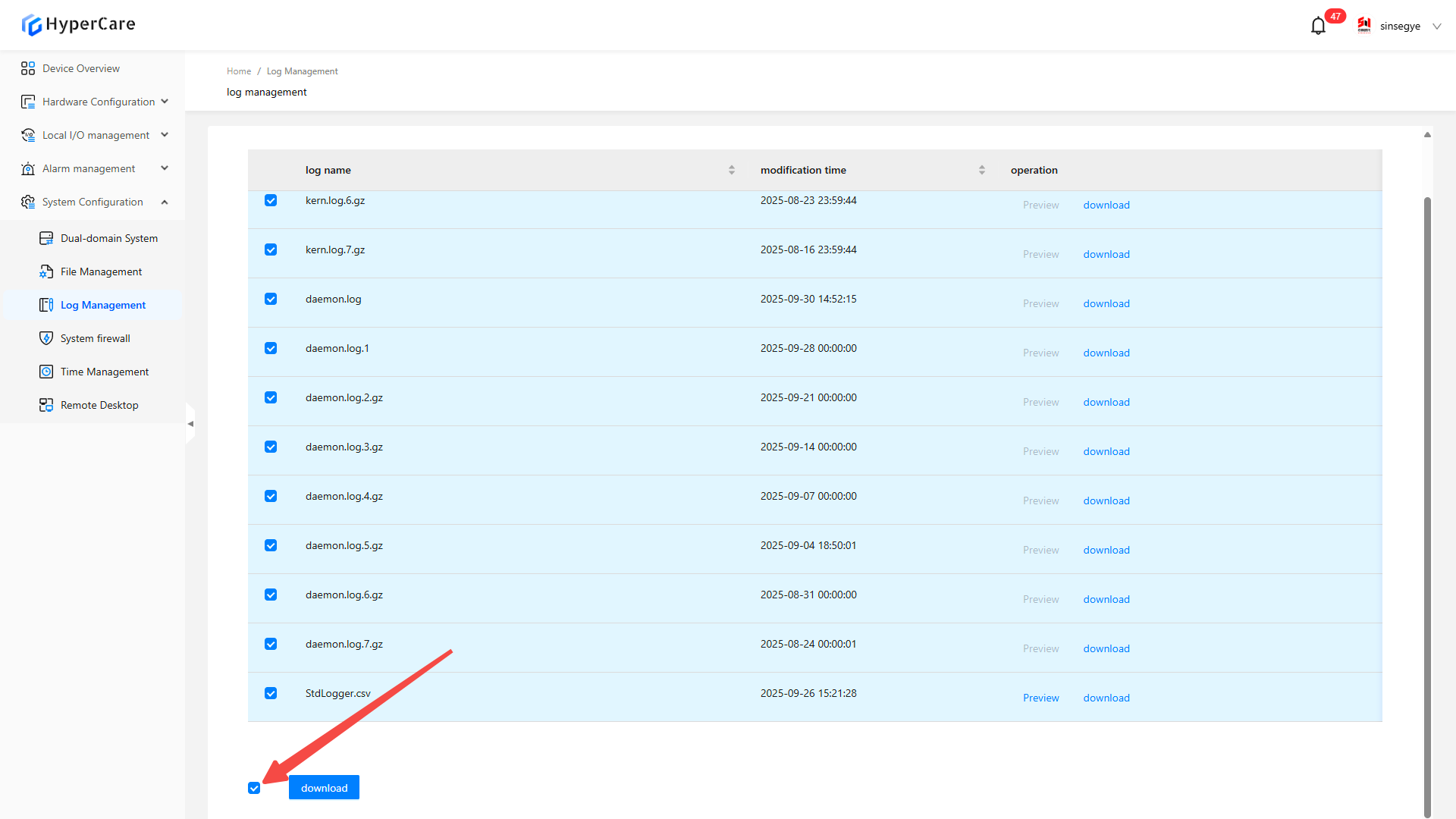
Click the \[Download] button at the bottom for batch download.
14.3.6 Sorting of logs
Support sorting by \[Log Name] or \[Modification Time]. Click the \[Arrow] button to toggle the sorting modes.
-
Descending order
-
Ascending order
-
No sorting
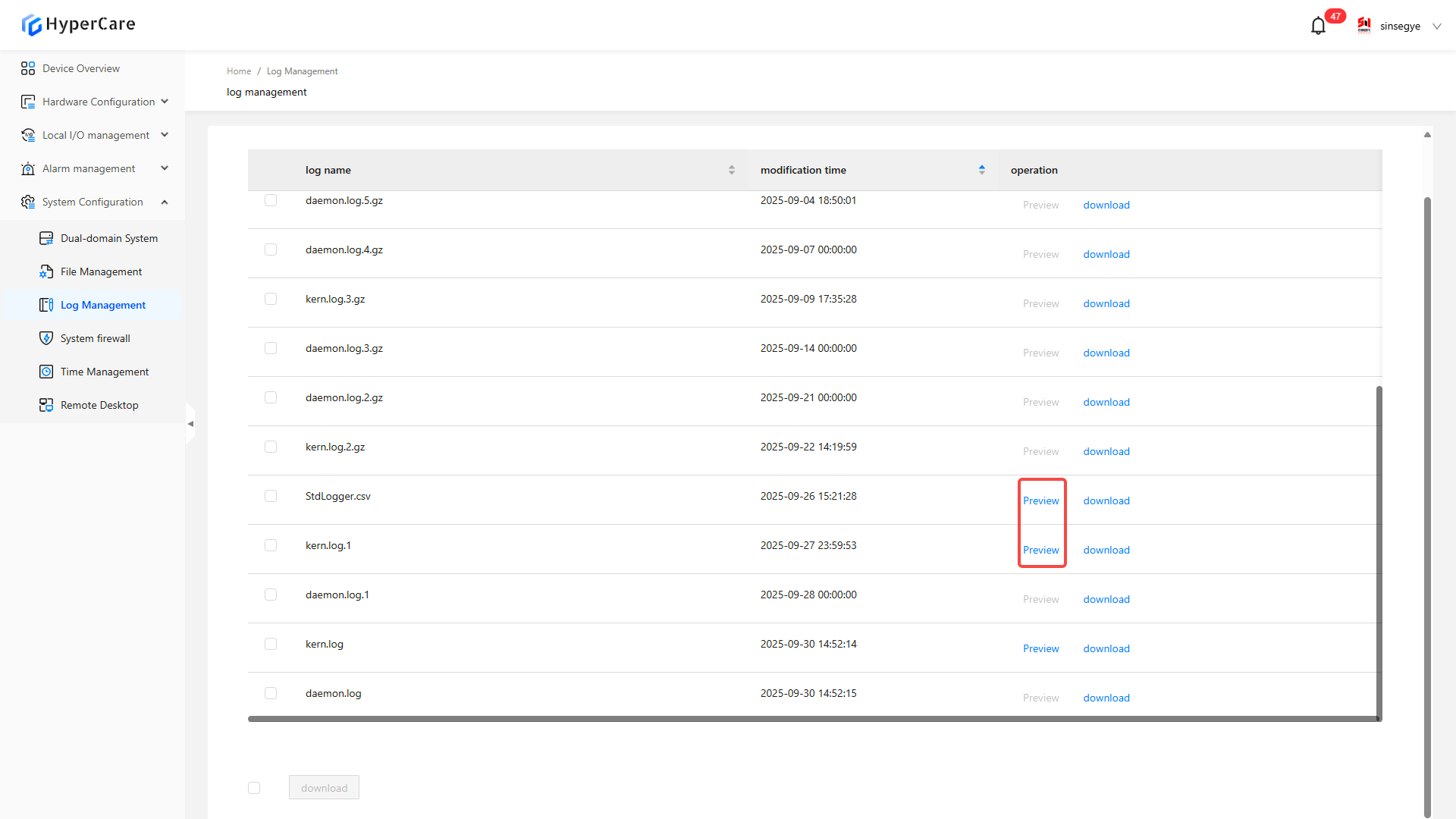
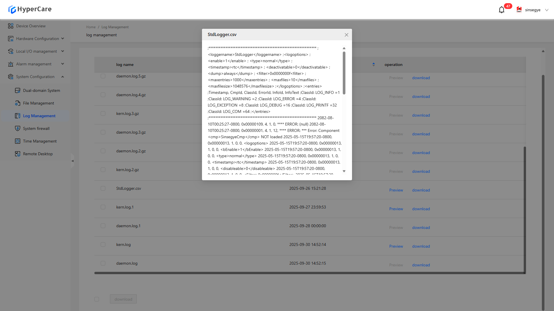
14.3.7 Preview of logs
Some logs can be previewed by clicking the \[Preview] button
14.3.8 Generate report
Click \[Generate Report] in the upper right corner
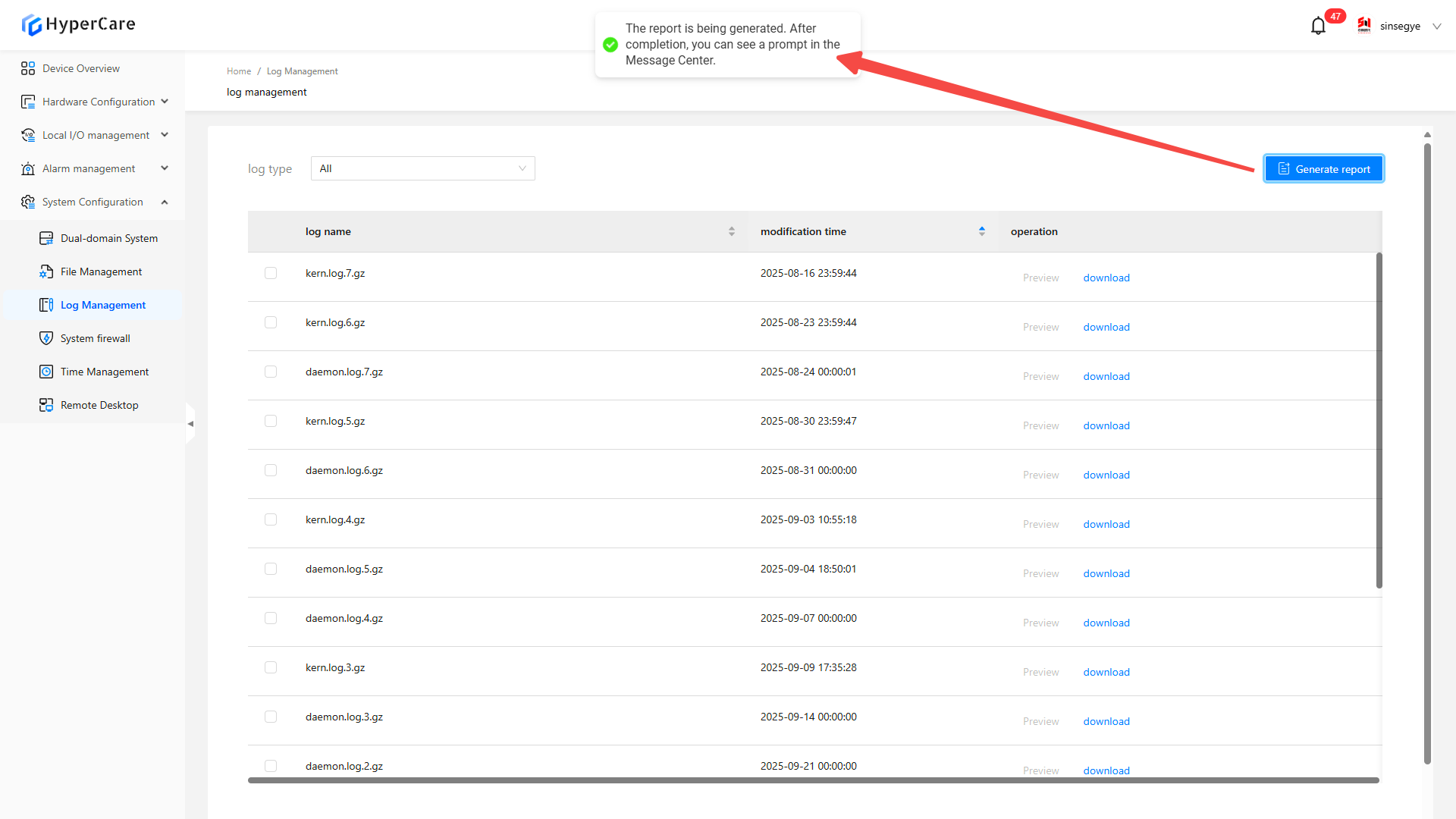
Message details can be viewed in the Message Center.
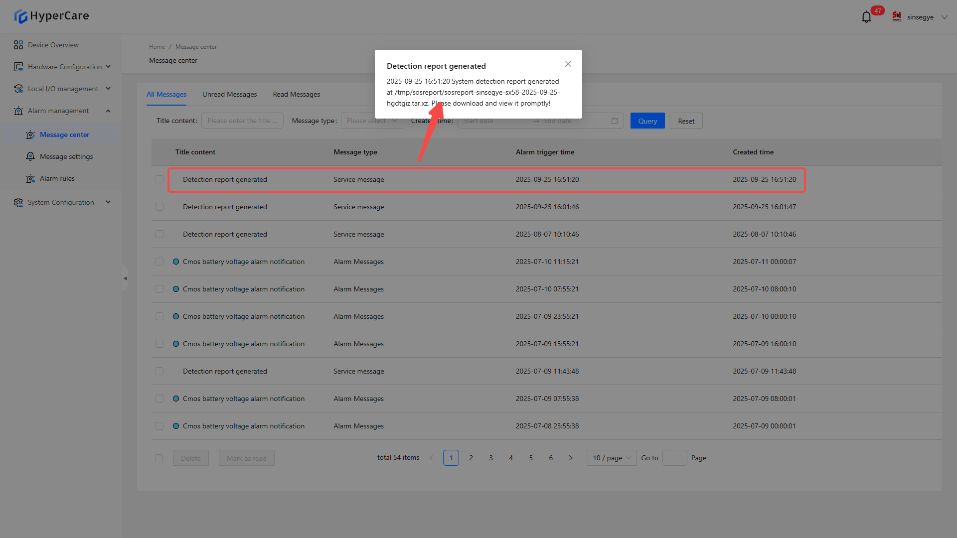
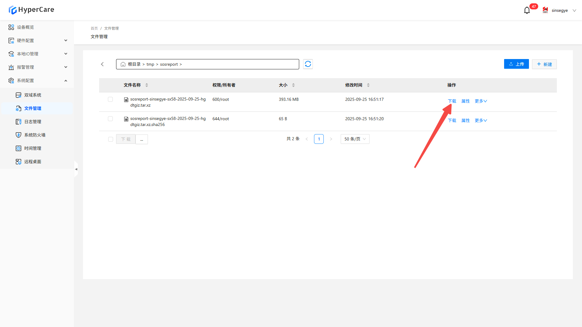
Follow the path in the message details to find the report document from file management.
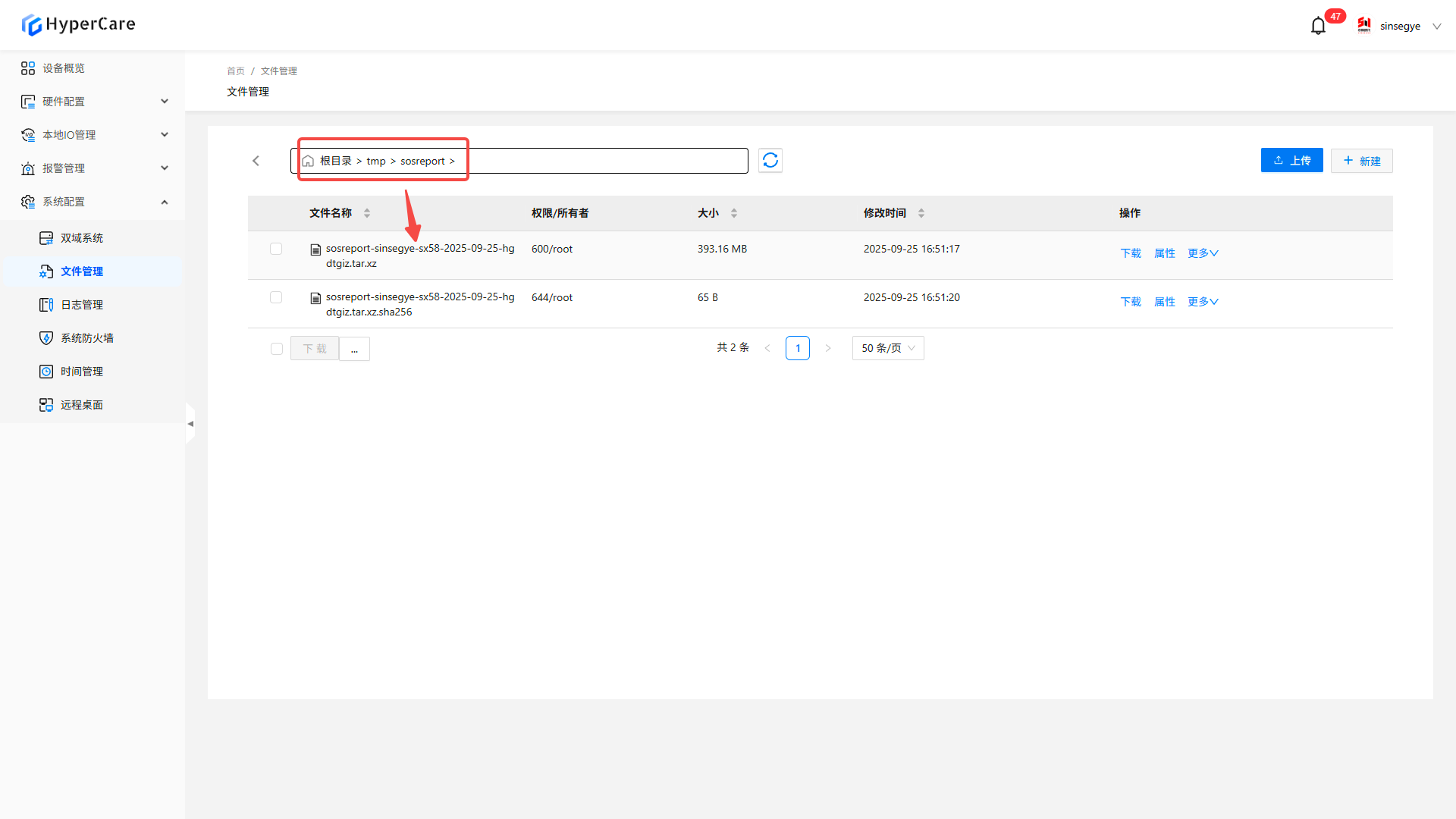
The report can be saved to the local computer by clicking \[Download]
15. System Configuration - System Firewall
15.1 Scope of Application
It is applicable to all adapted models.
15.2 Function Introduction
This function is used to provide refined network access control and threat defense capability.
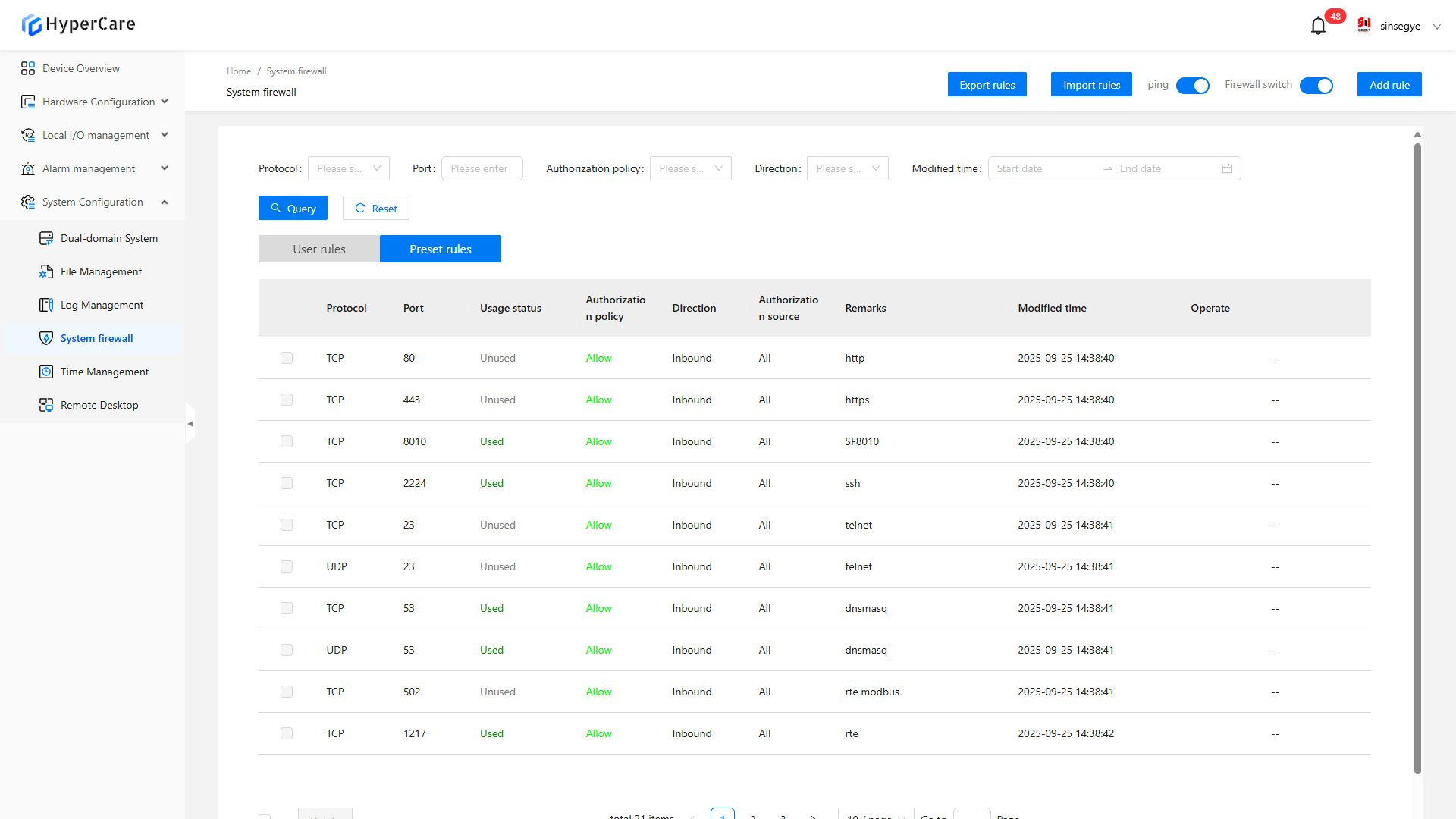
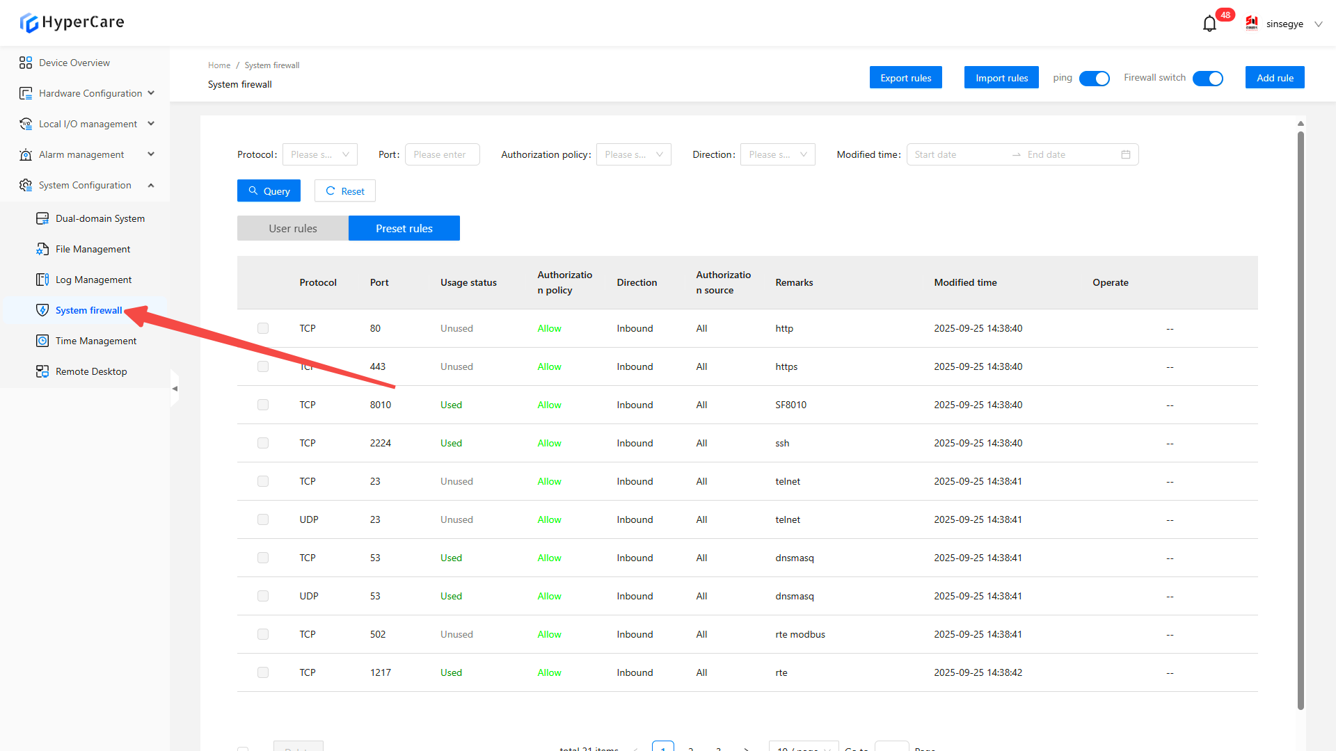
15.3 Usage Details
15.3.1 Enter the pag
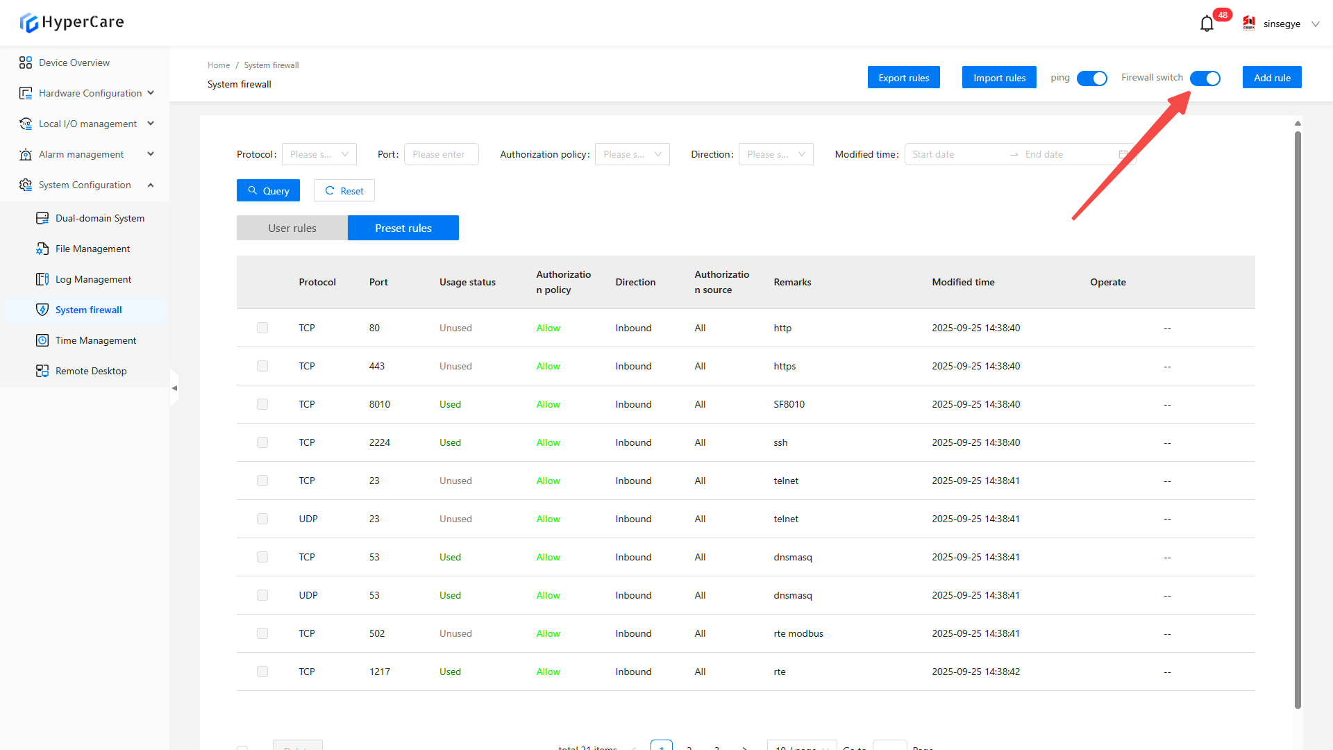
15.3.2 Firewall on-off control
Click \[Firewall Switch]
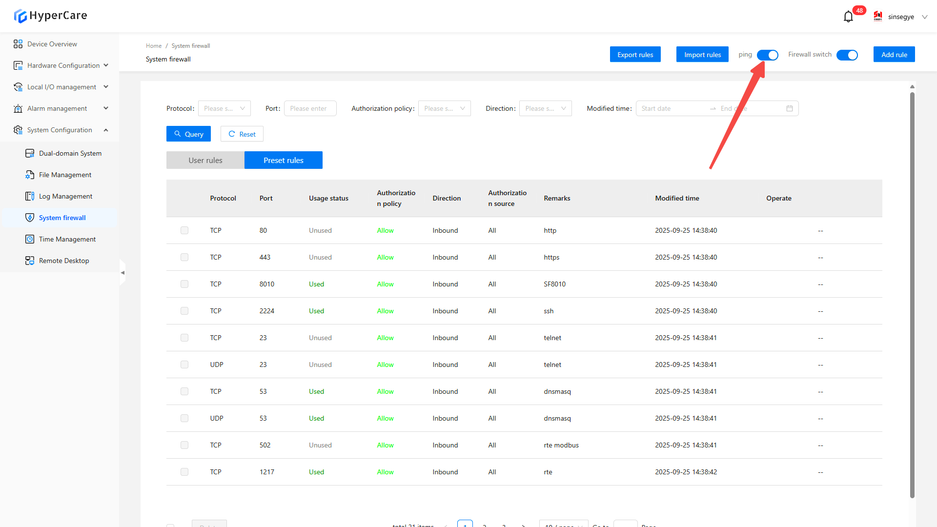
15.3.3 ping switch control
Click the \[Ping] switch to control whether ping is allowed.
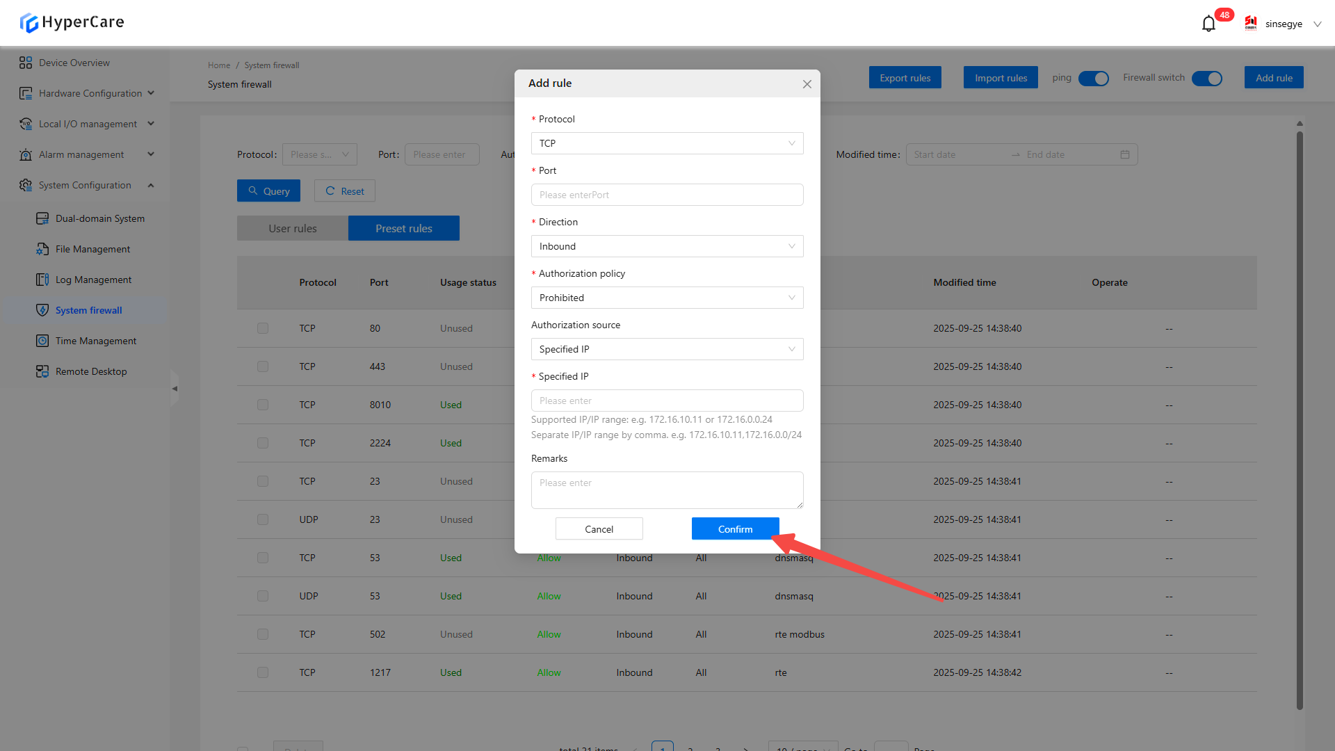
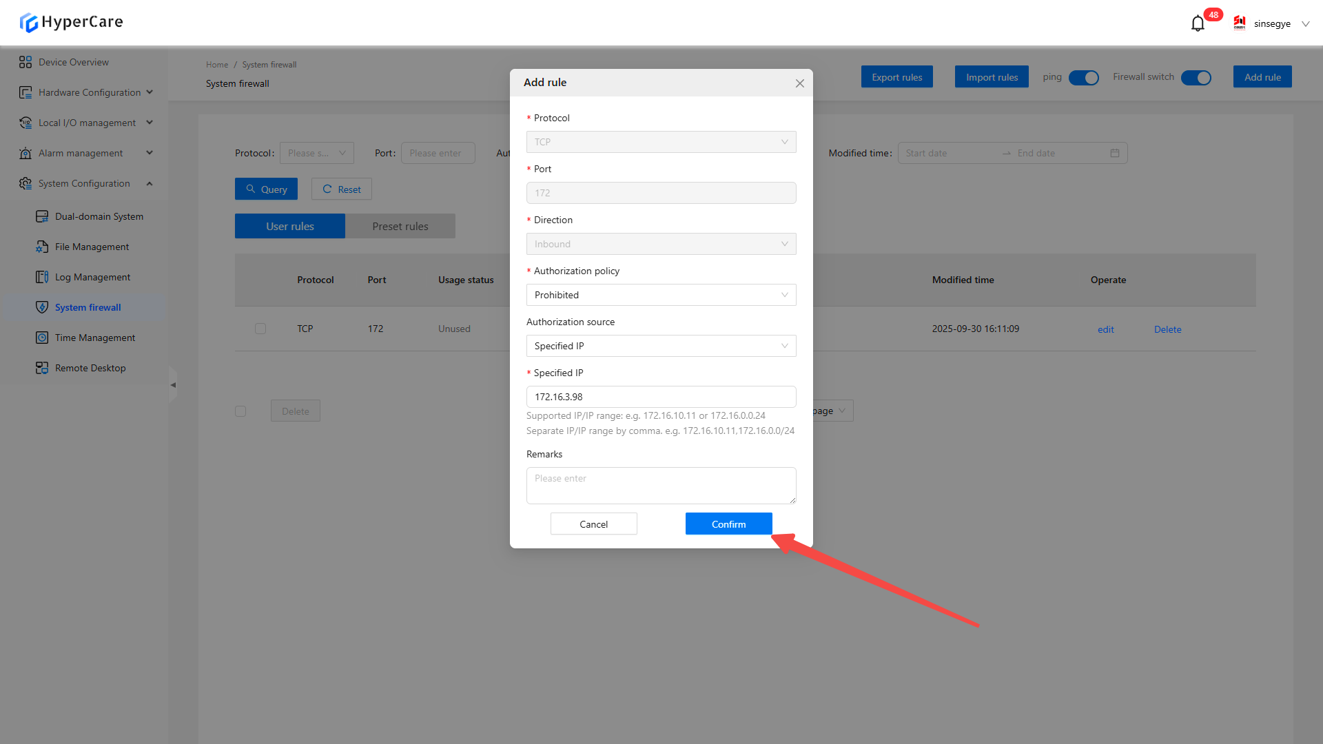
15.3.4 Add rule
Click \[Add Rule] in the upper right corner
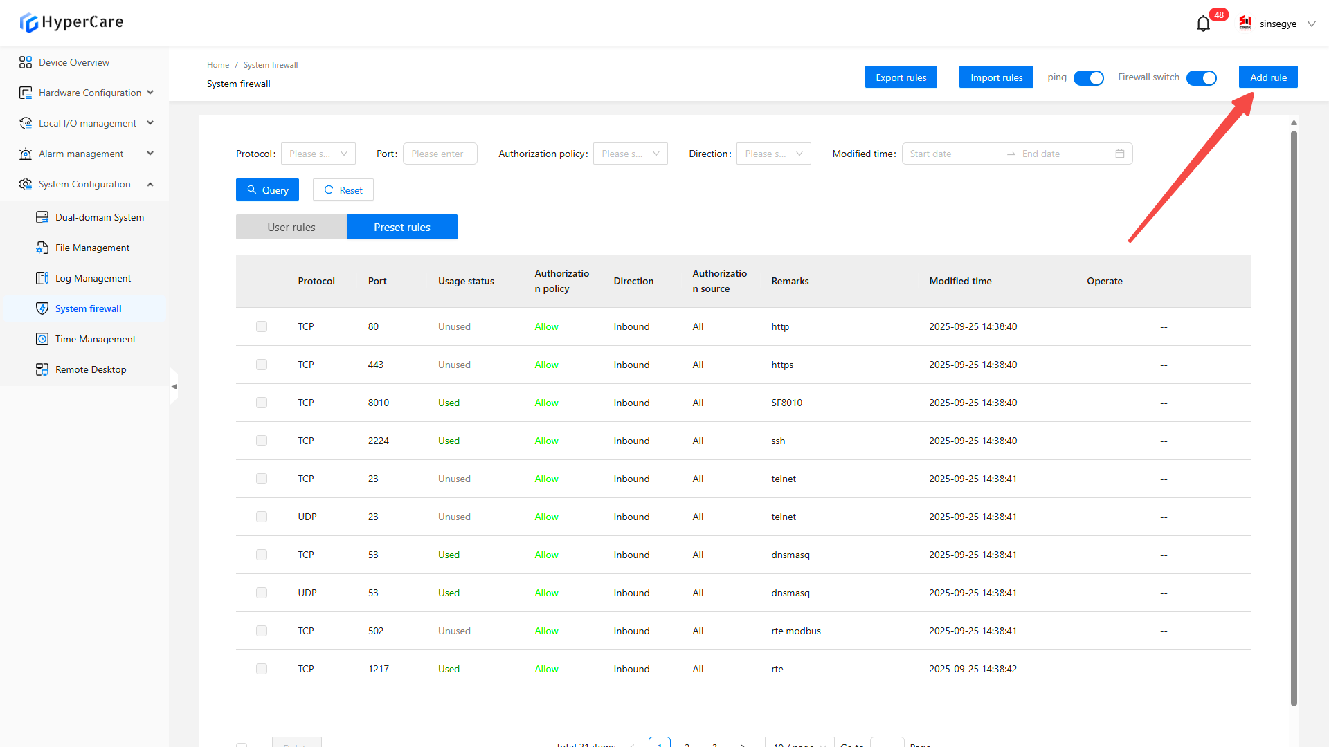
Enter rule information as prompted, click \[Confirm] to add it
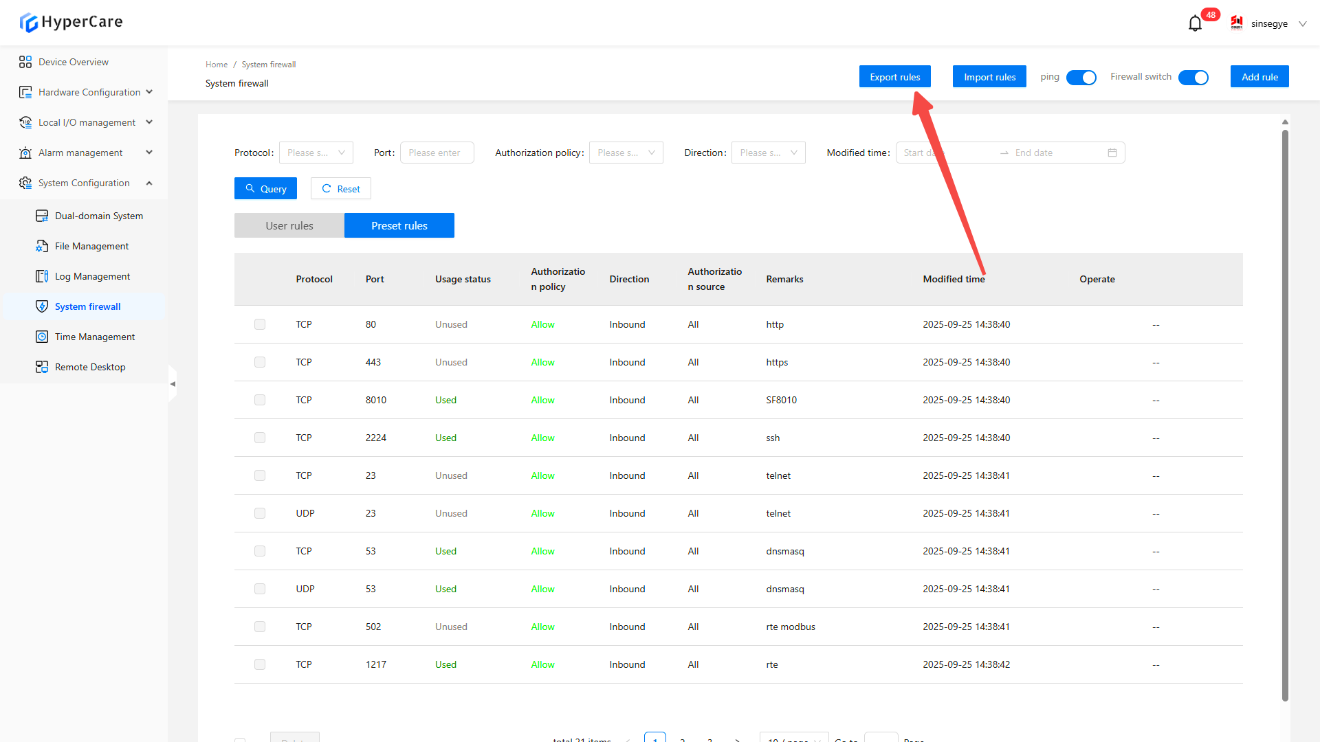
15.3.5 Export rules
Click \[Export Rules] to download the json file.
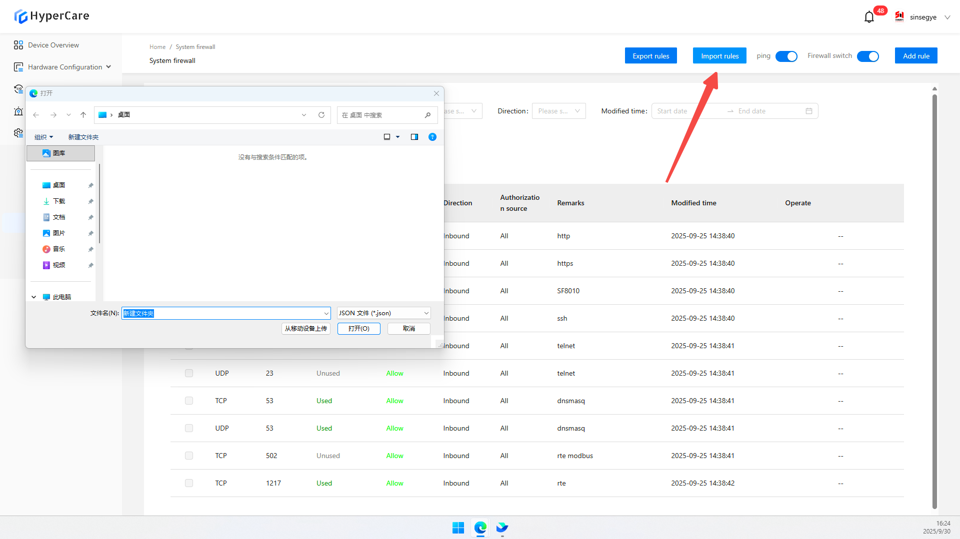
15.3.6 Import rules
Click \[Import Rules] to upload the json file.
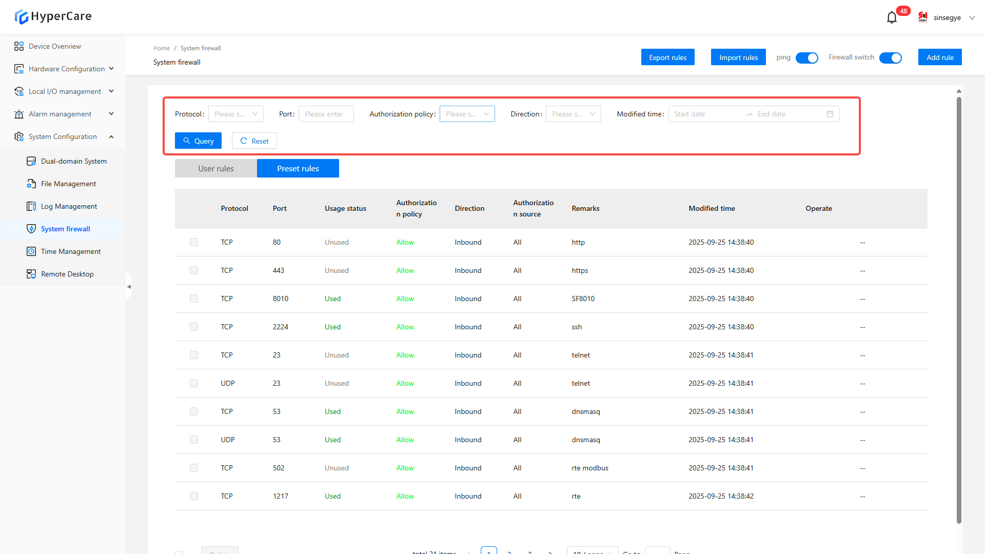
15.3.7 Filter and quer
You can search by protocol, port, authorization policy, direction, and modified time. Click the blue \[Query] button to apply the filter criteria, and click the white \[Reset] button to clear all filter criteria.
15.3.8 Rule editing and deletion
Click \[Edit]
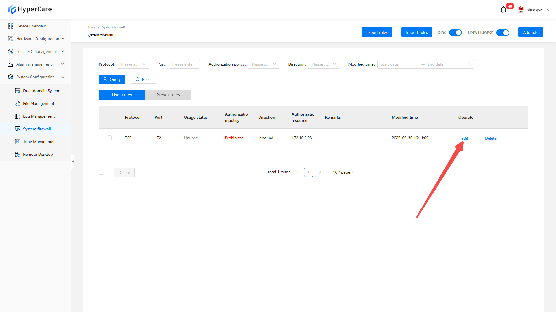
Click \[Confirm] to save.
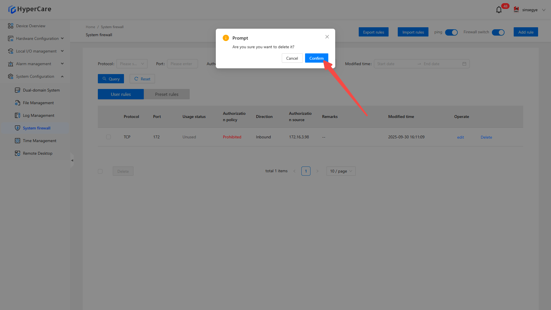
Click \[Delete].
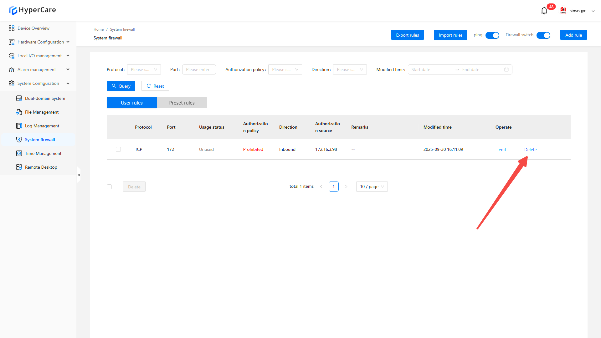
Click \[Confirm] to delete.
16. System Configuration - Time Management
16.1 Scope of Application
It is applicable to all adapted models.
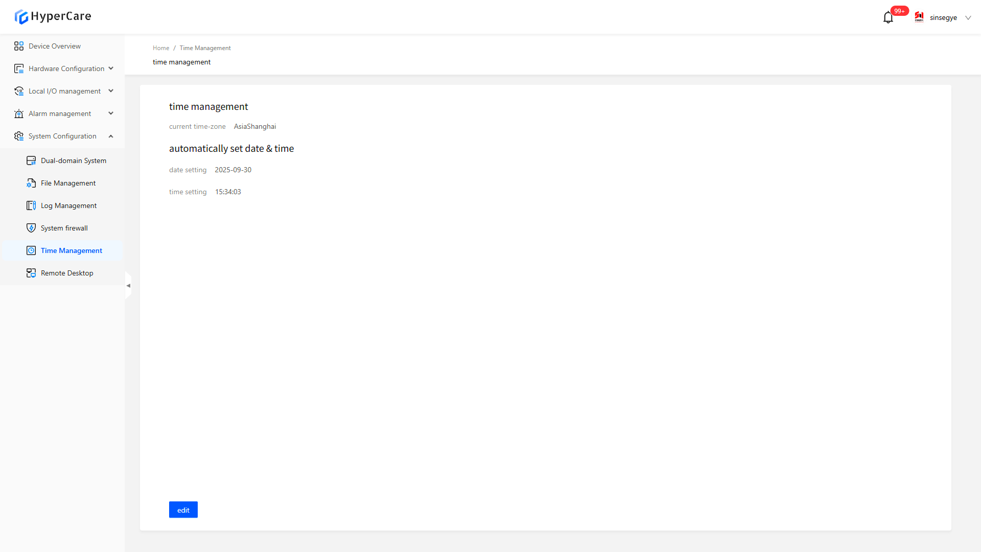
16.2 Function Introduction
This function is used to modify the time zone, date, and time settings of the real-time domain system.
16.3 Usage Details
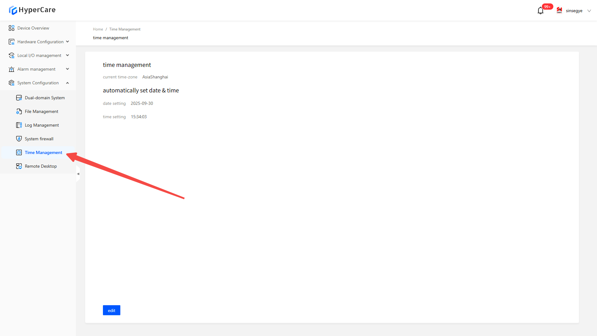
16.3.1 Enter the pag
| The time settings do not support automatic real-time update; you need to manually refresh the page to view the latest settings. |
|---|
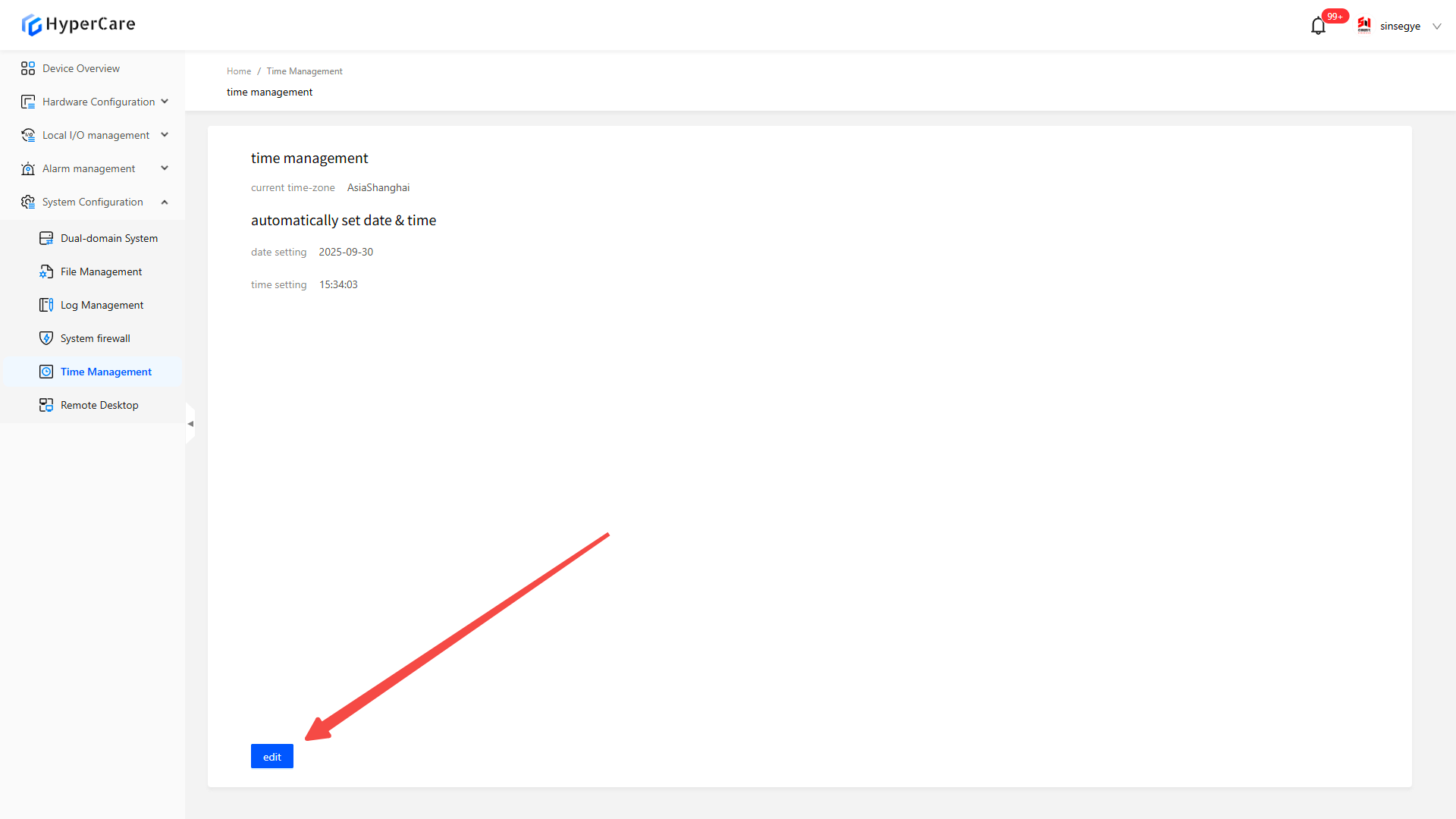
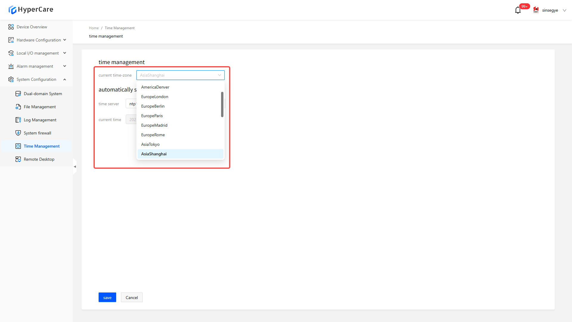
16.3.2 Modify the time zone
After clicking the \[Edit] button to enter the time editing interface.
Select an appropriate time zone based on on-site requirements.
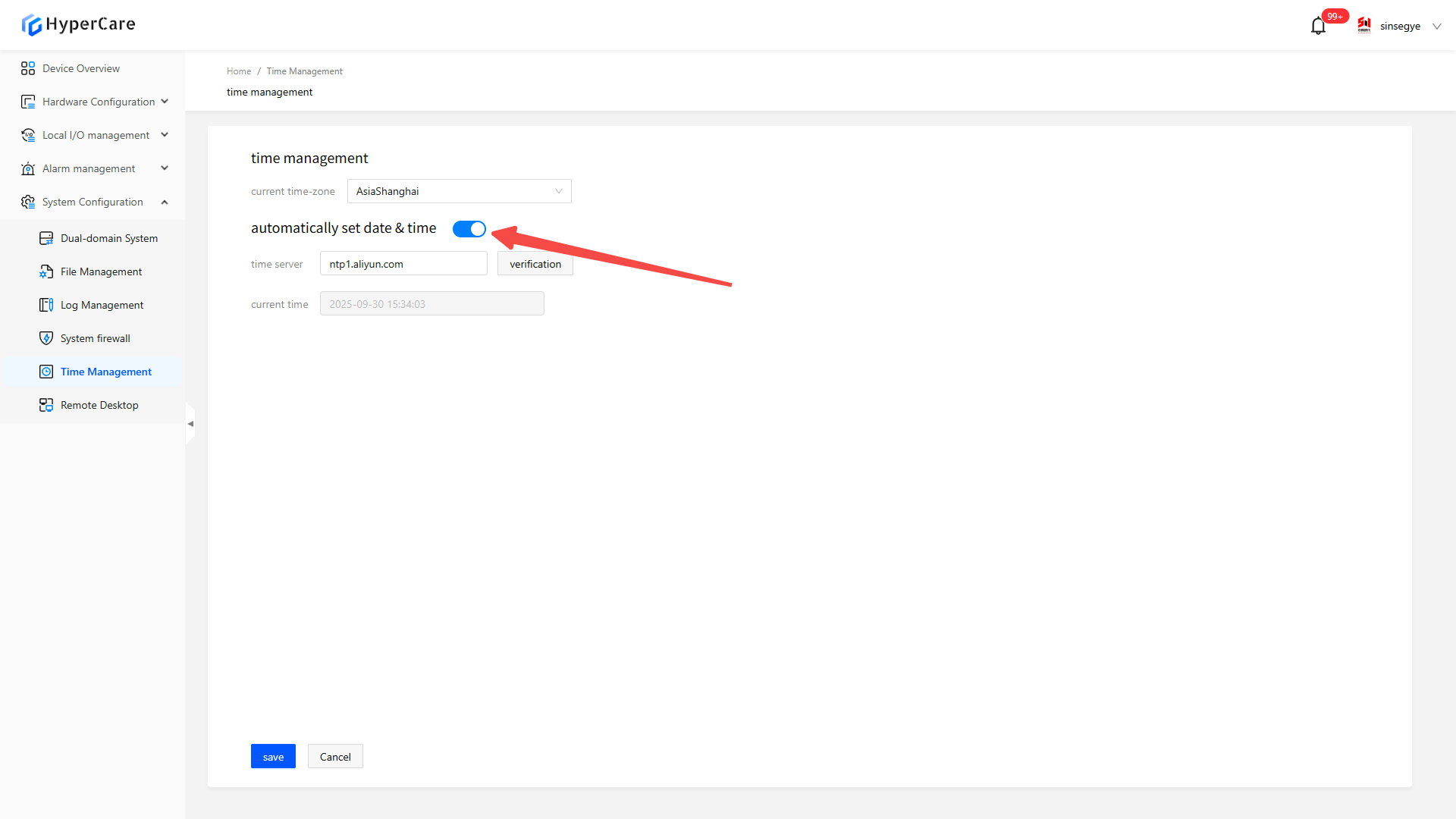
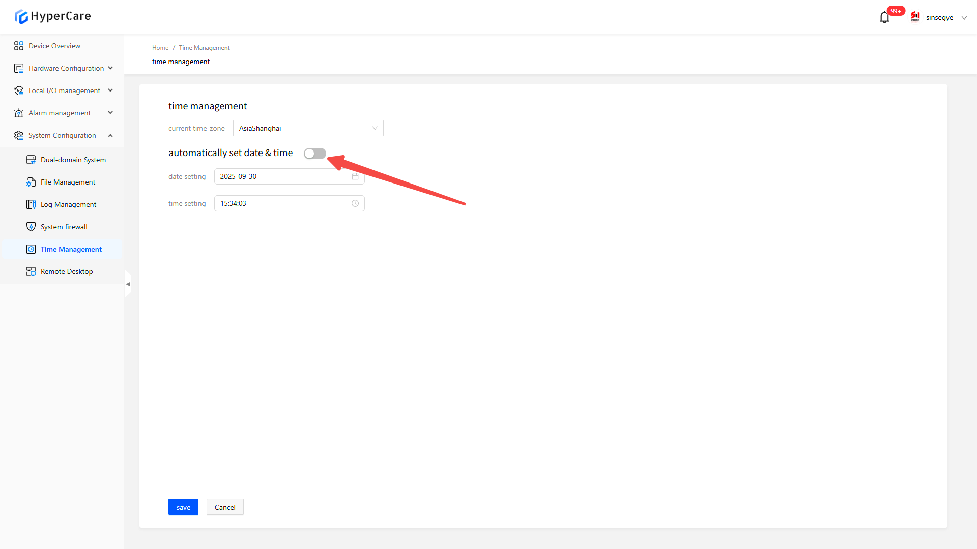
16.3.3 Automatically set date and time
After selecting the time zone, click \[Slider] to check \[Automatically Set Date and Time]
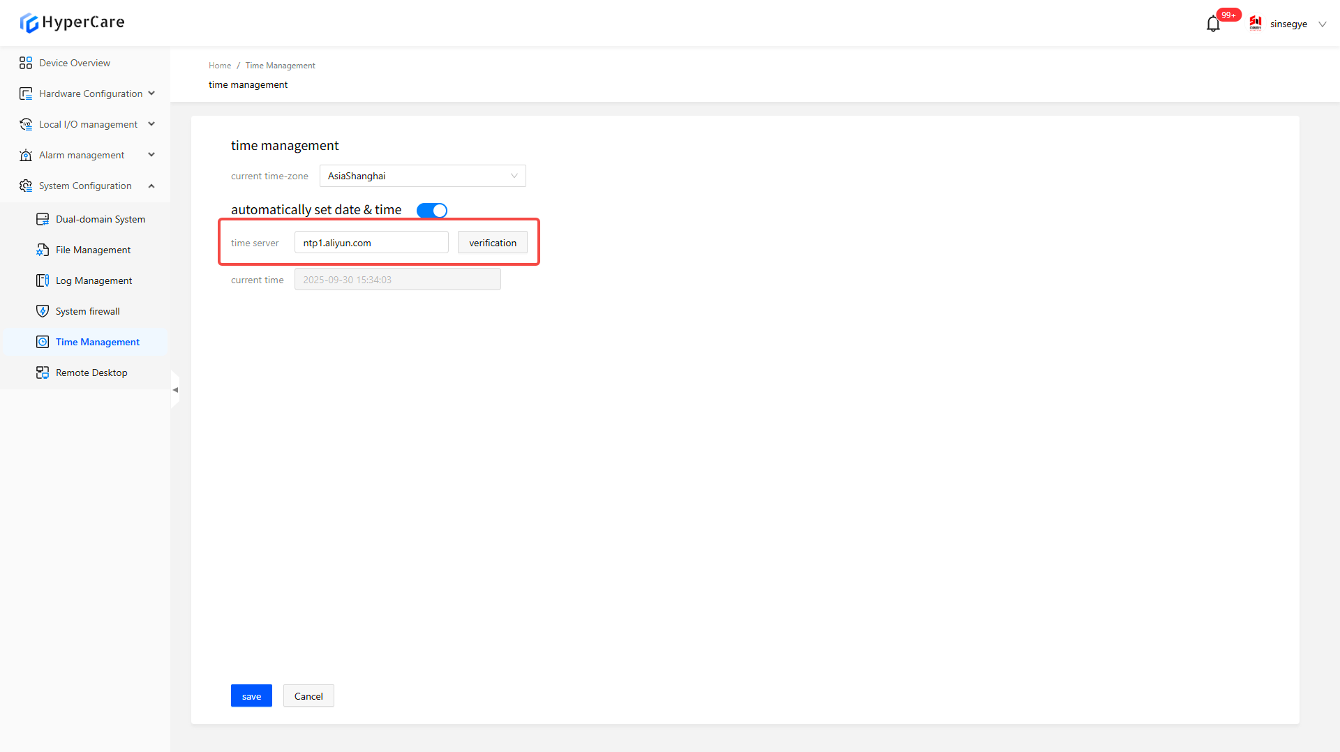
Enter a time server address and click \[Verify].
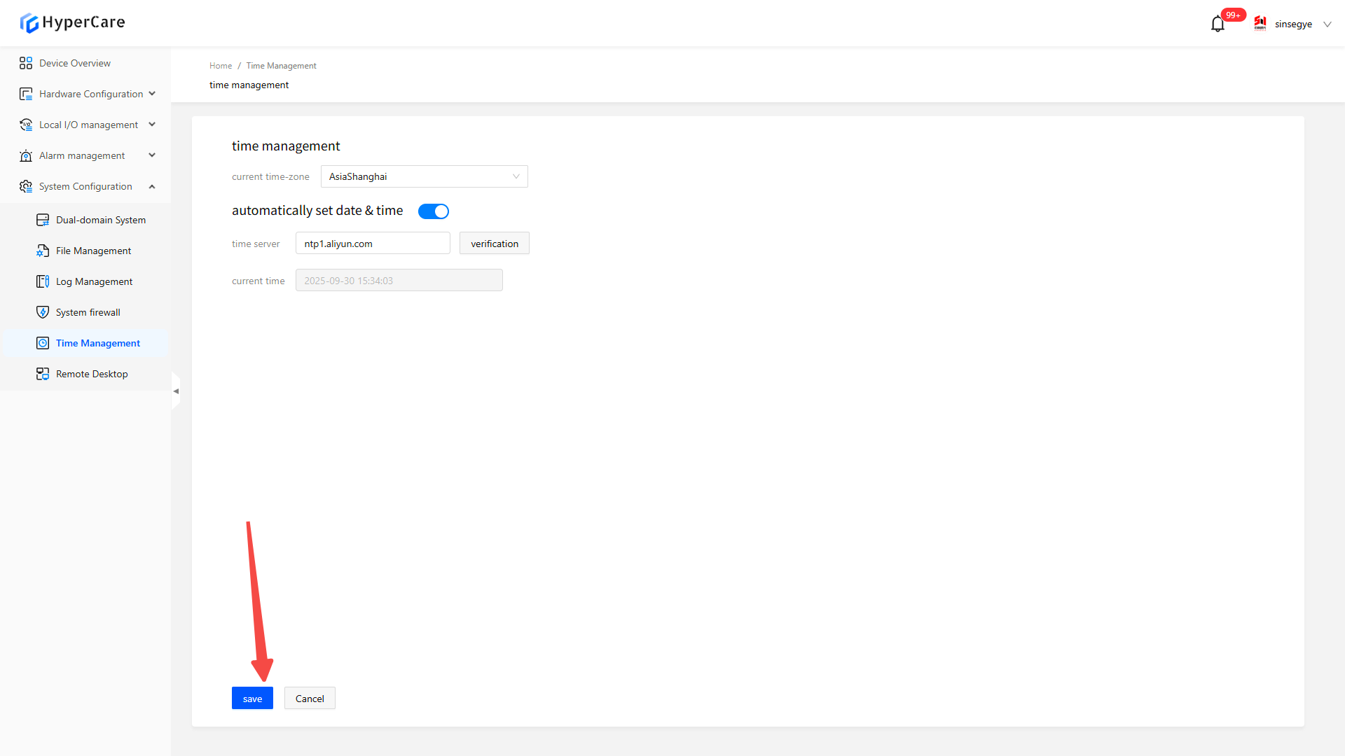
After completing the configuration modification, click \[Save] to apply the settings.
16.3.4 Manually modify the date and time
After selecting the time zone, click \[Slider] to close \[Automatically Set Date and Time]
Click the date setting dropdown menu
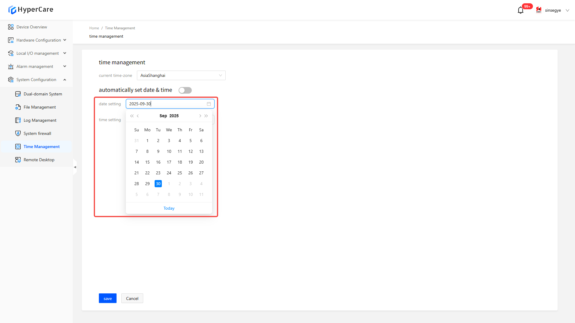
Click \[Today] to select the current date
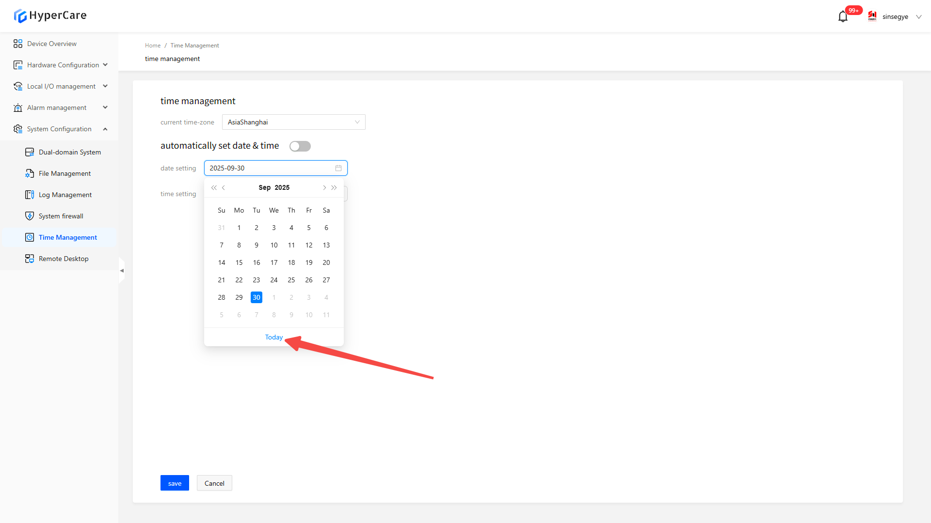
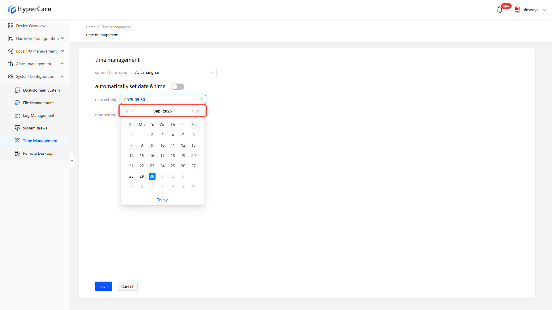
Use the \[<<] or \[>>] double arrows in the dropdown menu to adjust forward/backward by year, and use the \[<] or \[>] single arrows to adjust forward/backward by month.
Click the time setting dropdown menu
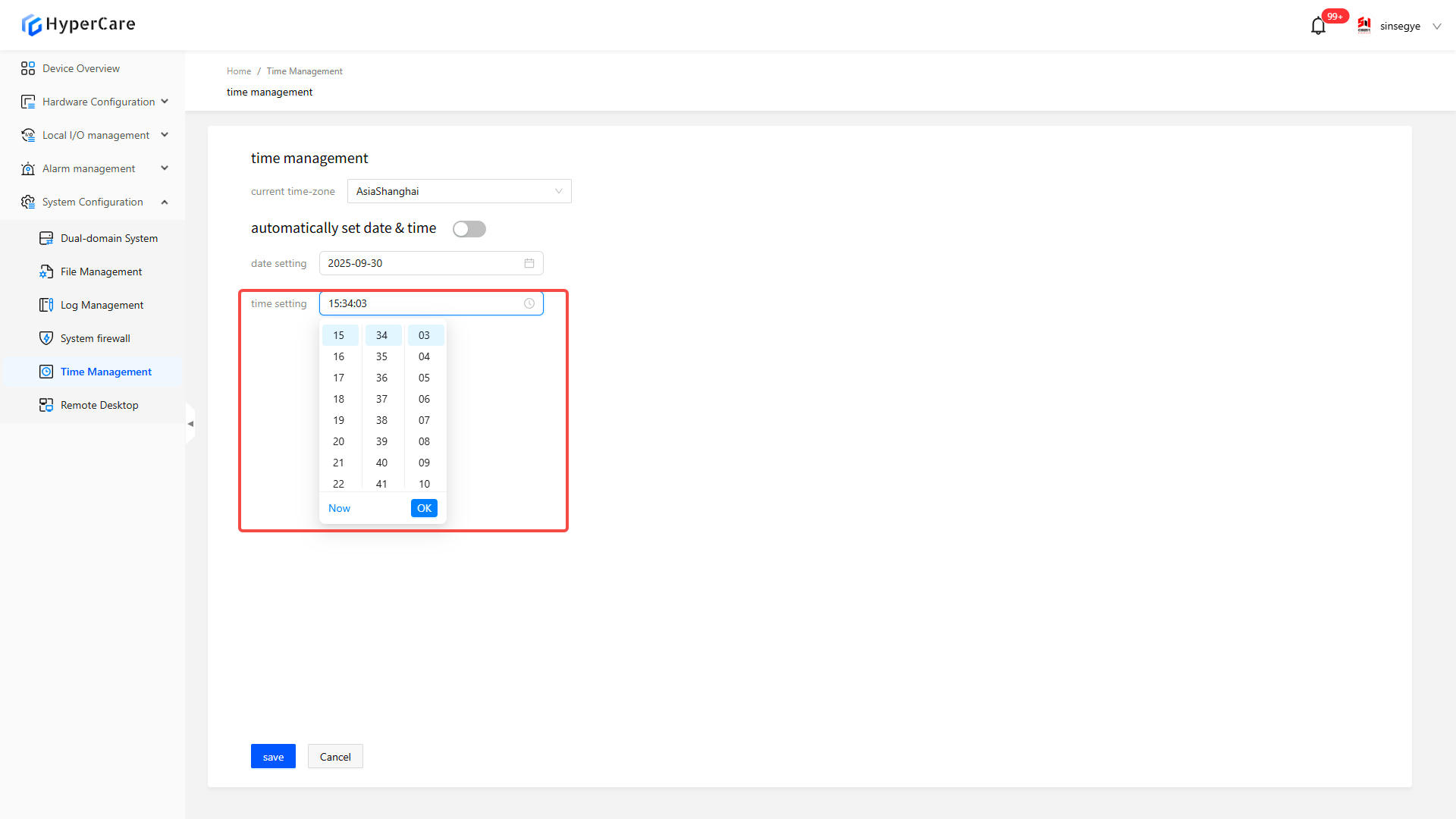
Click \[Current Time] to select the current time
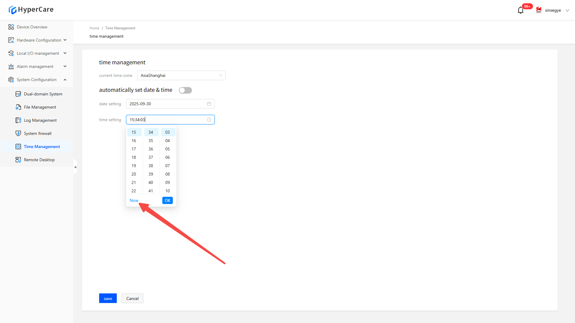
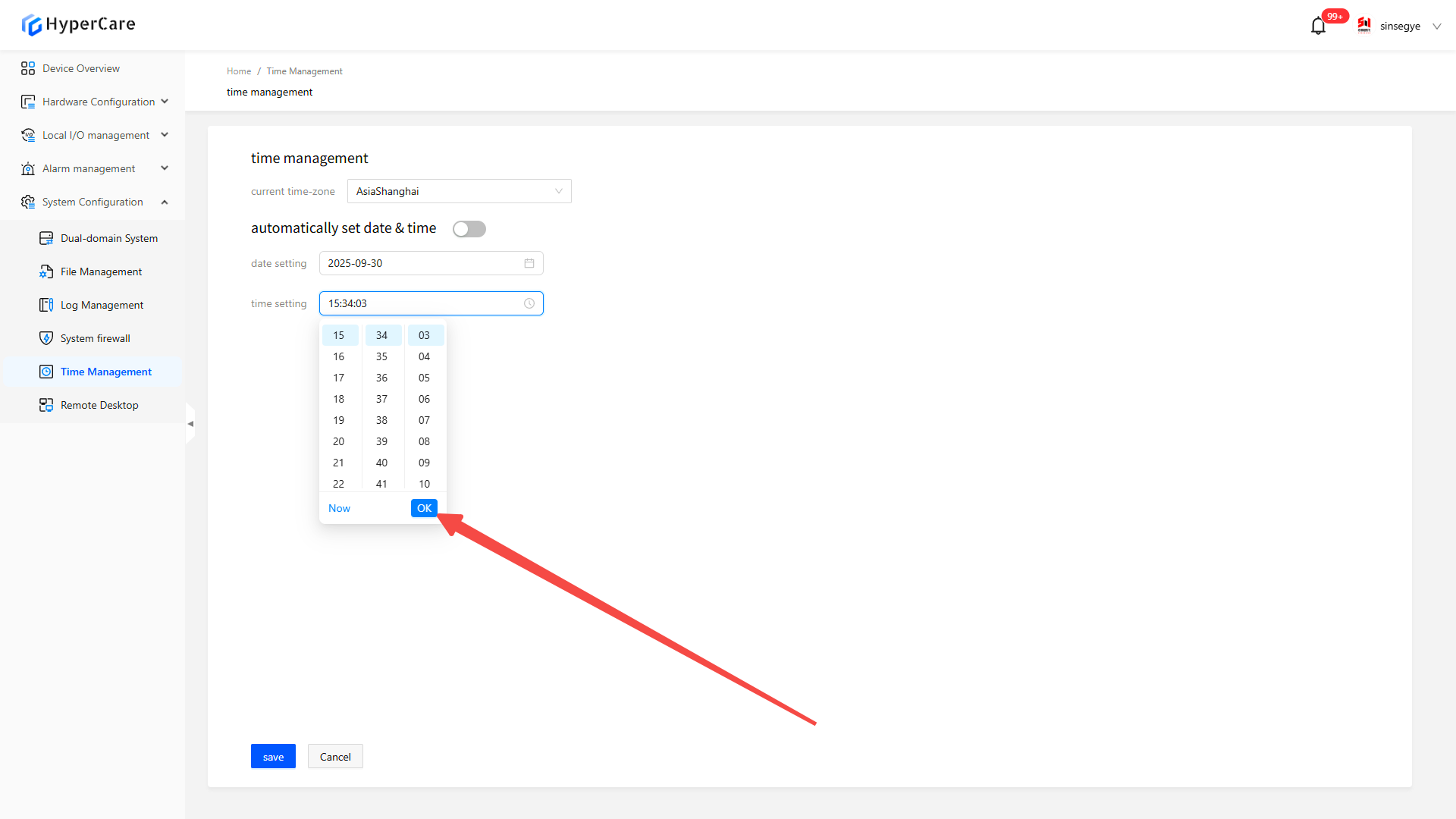
After selecting the time by the mouse wheel, click the \[OK] button
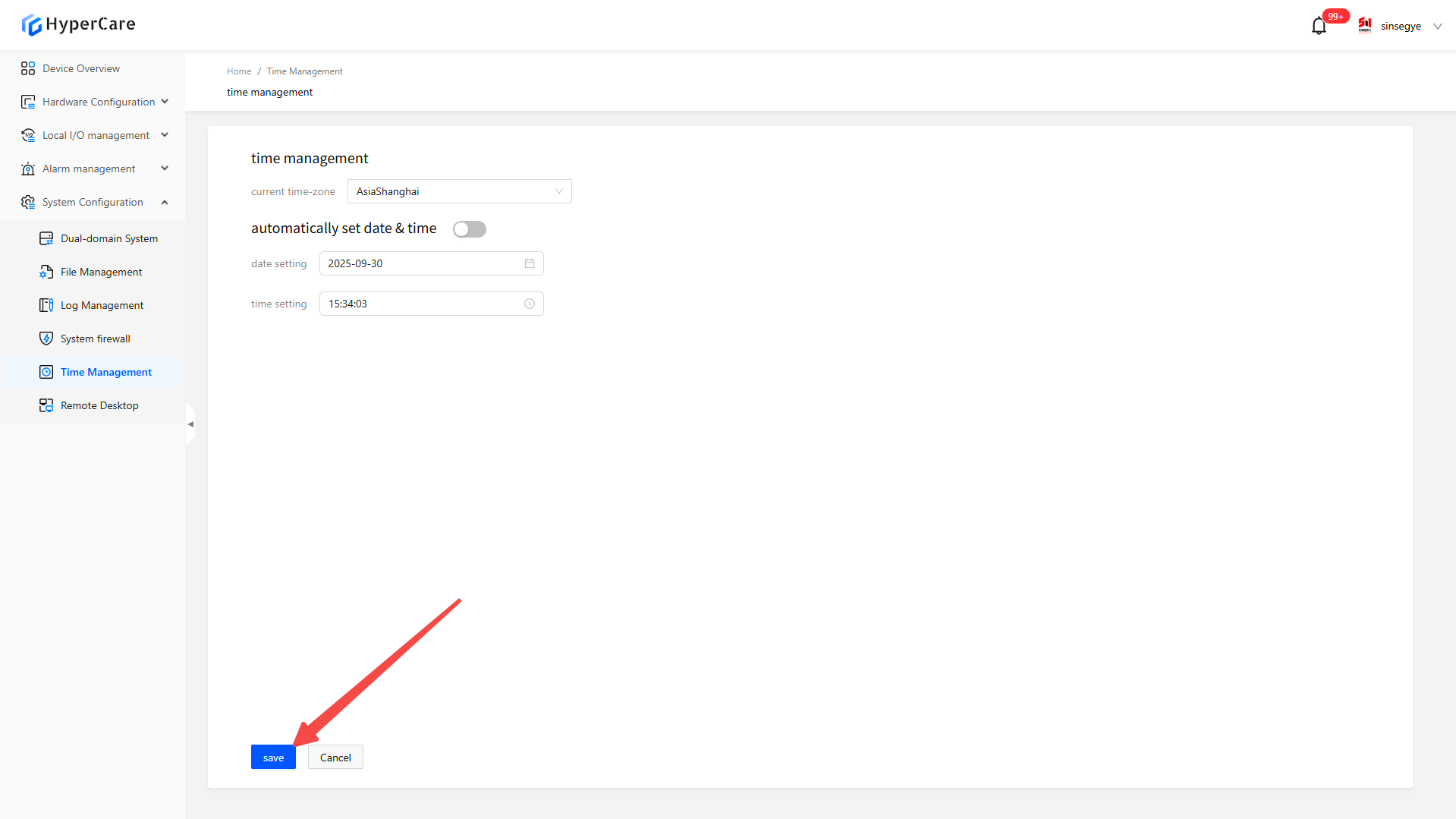
After completing the configuration modification, click the \[Save] button to apply the settings.
16.3.5 Important notes
-
The time does not support automatic real-time update; you need to manually refresh the page to view the latest settings.
-
Even if only partial configurations are modified, the final effective settings are determined by the time zone, date, and time displayed on the page, and the modification must be confirmed by clicking \[Save].
-
Please perform the configuration modifications in a non-production environment.
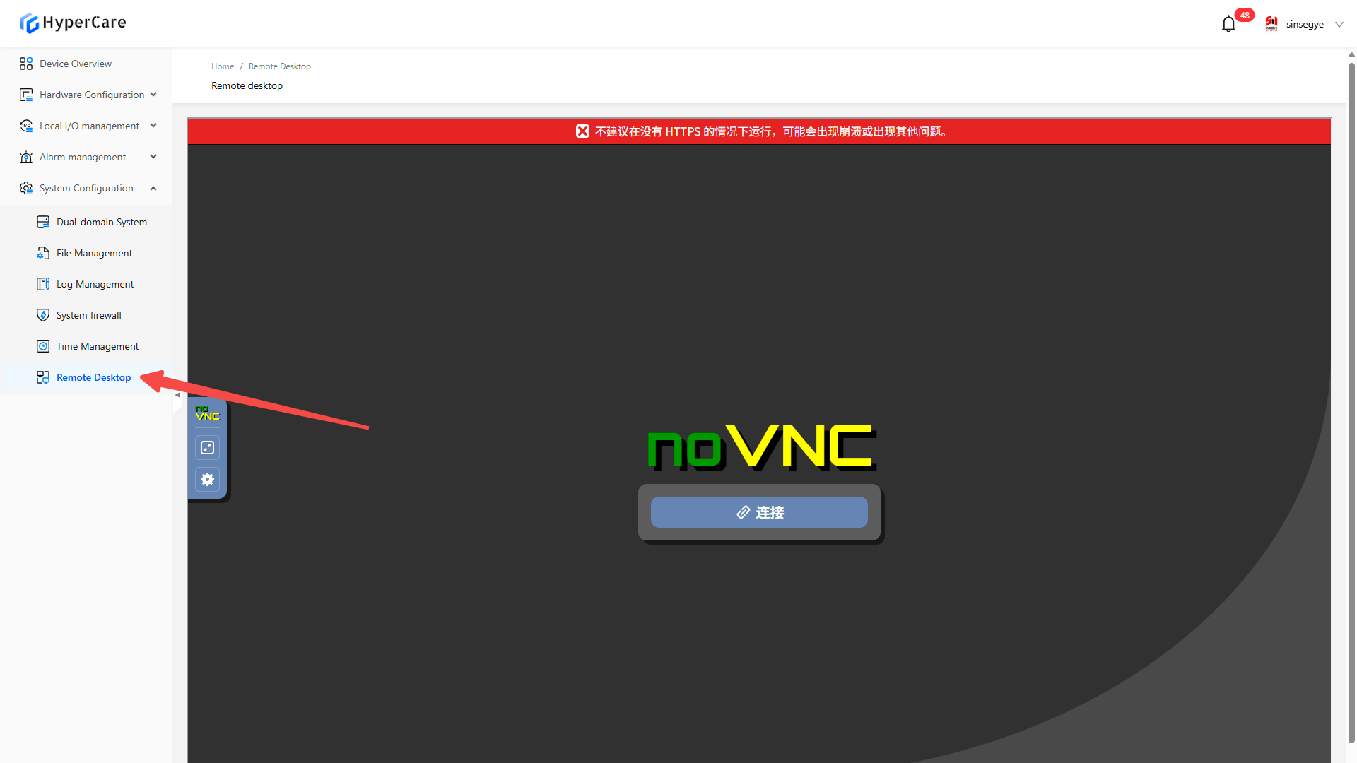
17. System Configuration - Remote Desktop
17.1 Scope of Application
| SX58 series | SX51XX-10XX series | SX51XX-11XX series | SX51XX-20XX series | SX2133 Type I |
|---|
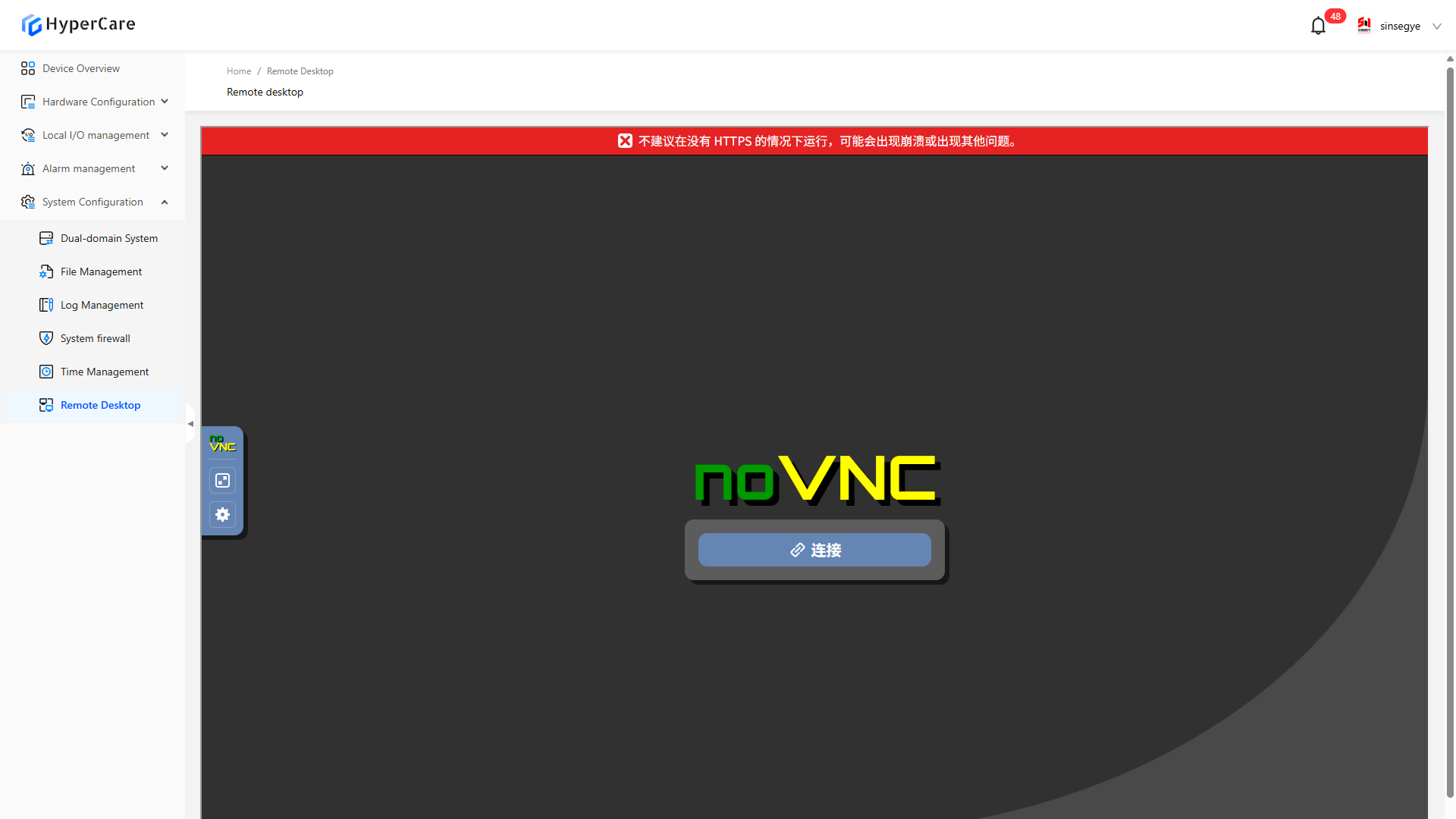
17.2 Function Introduction
This function is used for the user to directly operate the graphical interface of the remote host on local terminal device through network
17.3 Usage Details
17.3.1 Enter the page
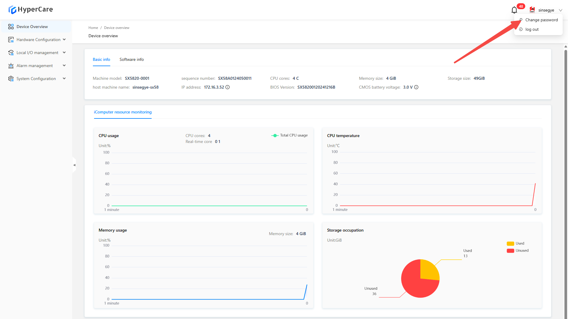
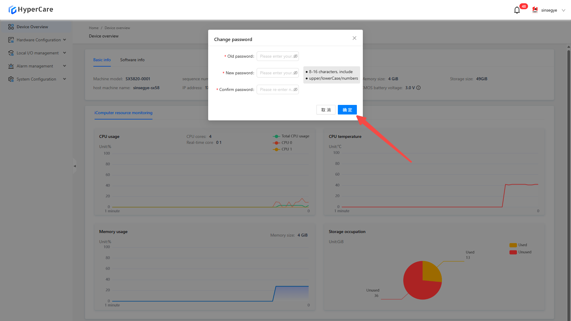
18. Modify Password
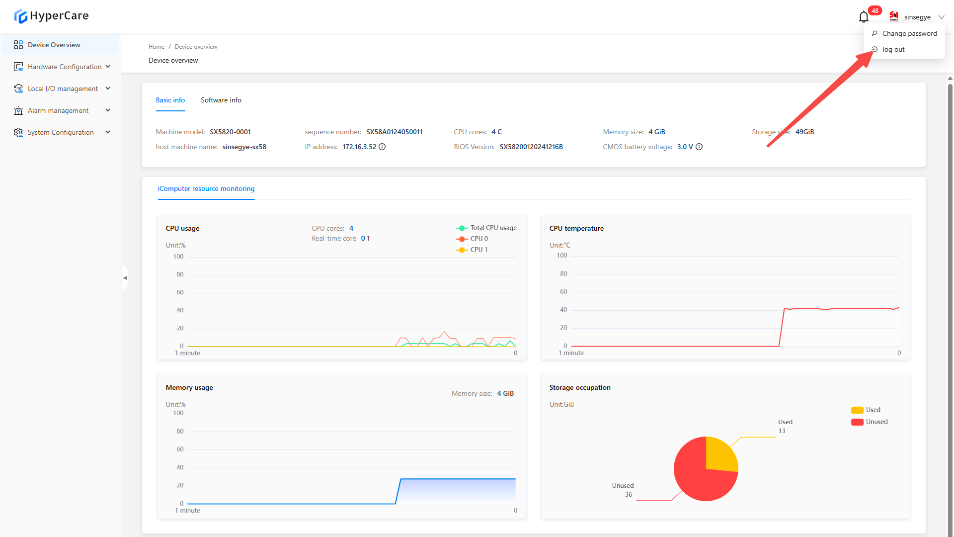
Click \[Modify Password] at the right upper corner.
Enter \[Old Password] and \[New Password]
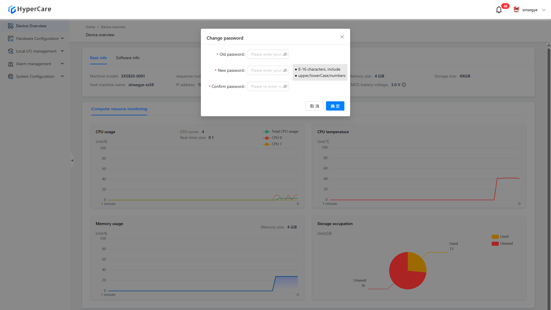
Click \[Confirm] to change the password
Appendix
1. Error Diagnosis
Most issues arising from the software can be resolved through the following two methods.
1.1. Log out
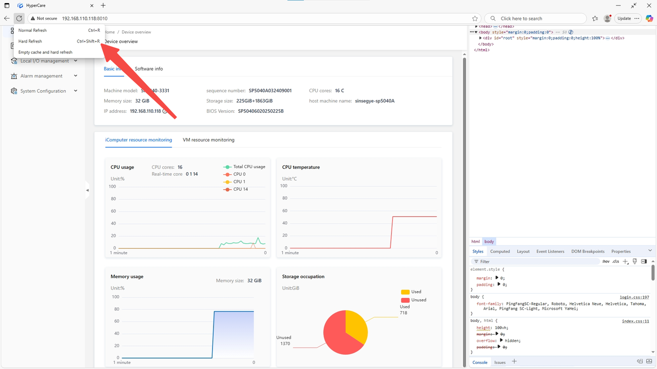
2. Refresh
Press \[F12] to enter the developer interface
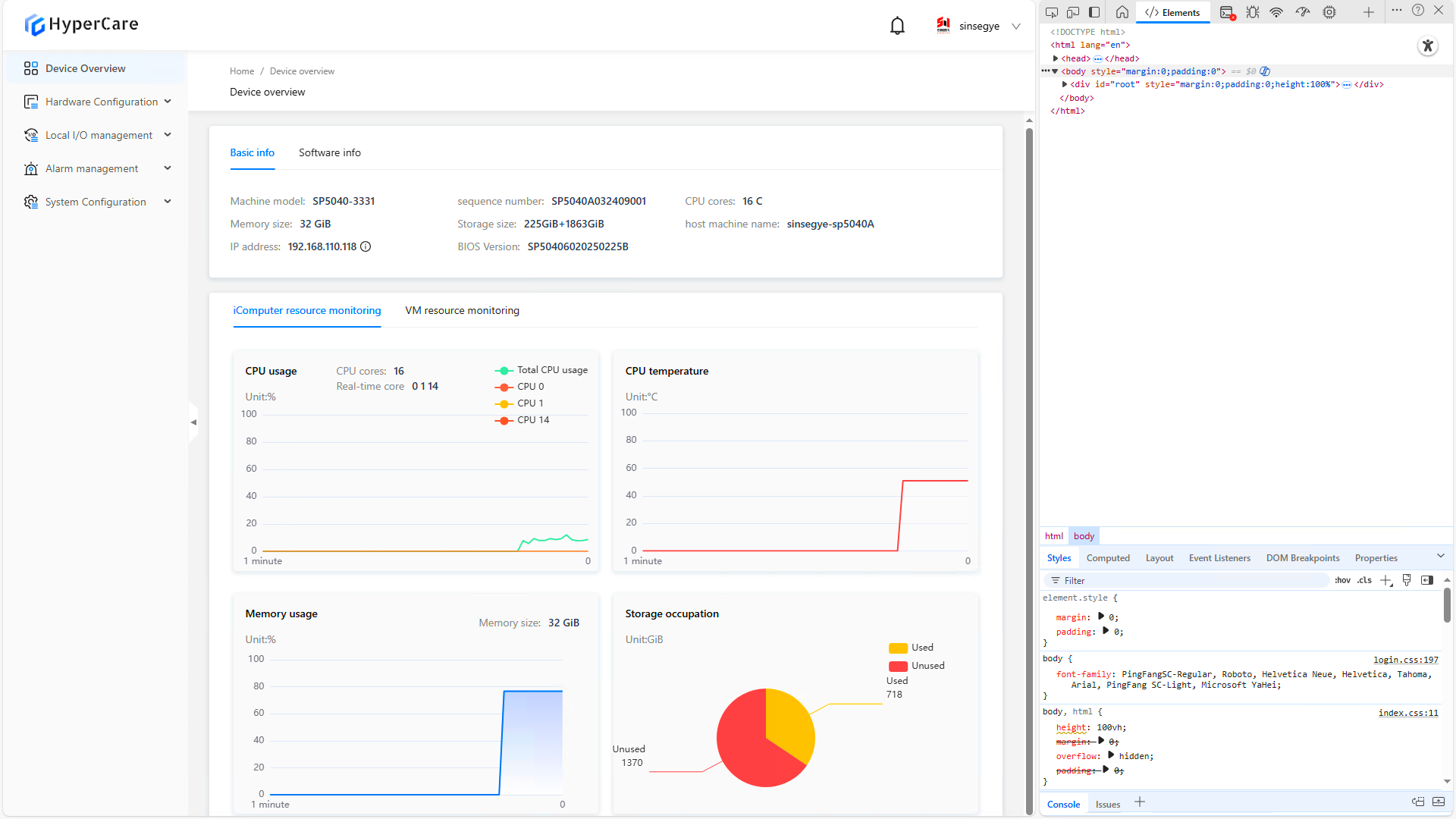
Right-click the \[Refresh] button and then select \[Hard Refresh]