Introduction to IOTHub Functions
Login Page
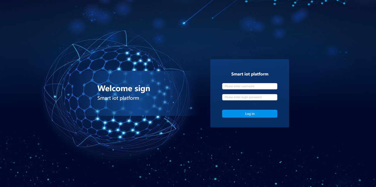
1. Function Overview
This interface serves as the login entry for the intelligent IOT platform, realizing user identity verification through a simple interface design to ensure the security of device operations and data management.
2. Operation Process
2.1 Accessing the System
Display resolution ≥ 1920×1080, and access via a Google kernel browser (version ≥ 92):
Industrial intelligent computer IP address: 20021 (e.g., 192.168.111.174:20021)
2.2 Identity Verification
Step 1: Enter the employee number/registered account in the Username input field.
Step 2: Enter the corresponding password in the Password input field (password is hidden by default).
Step 3: Click the blue Login button to submit for verification.
Auxiliary Functions (General)
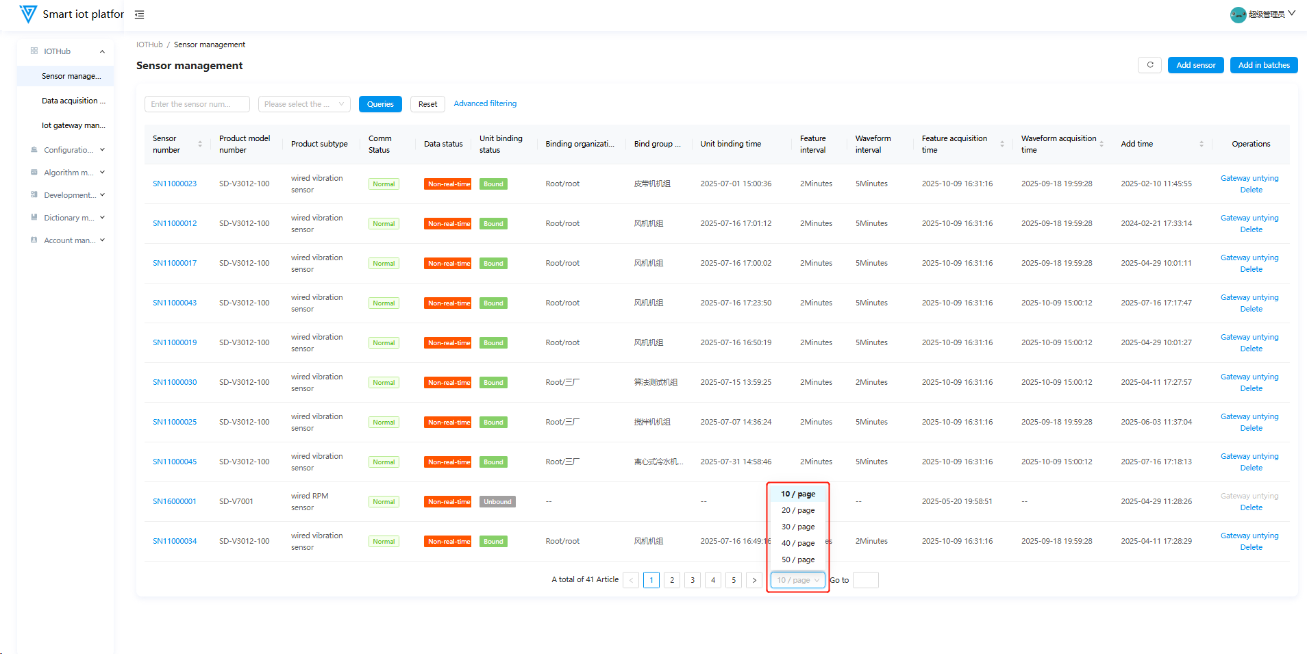
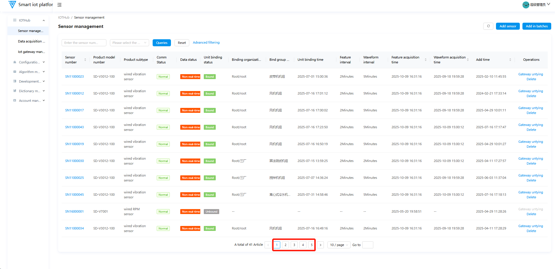
1. Pagination Control
1.1 Pagination Capacity
Switchable to display 10/20/30/40/50 pieces of information per page.
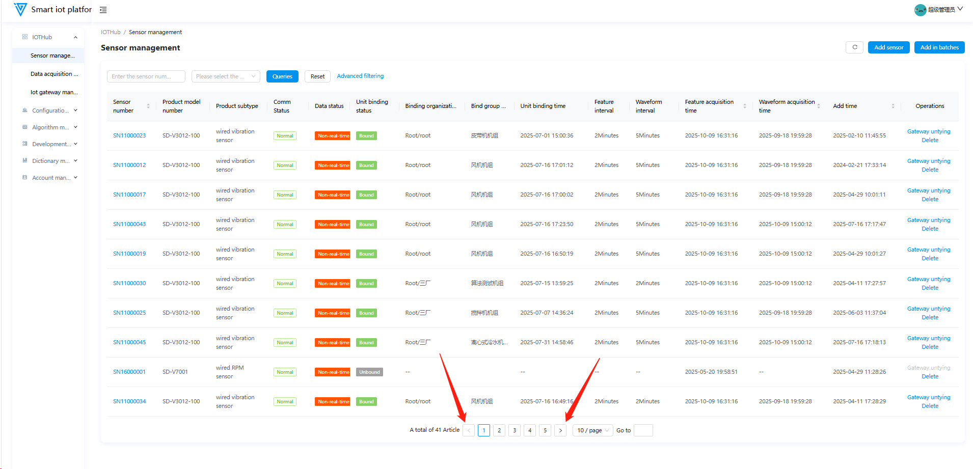
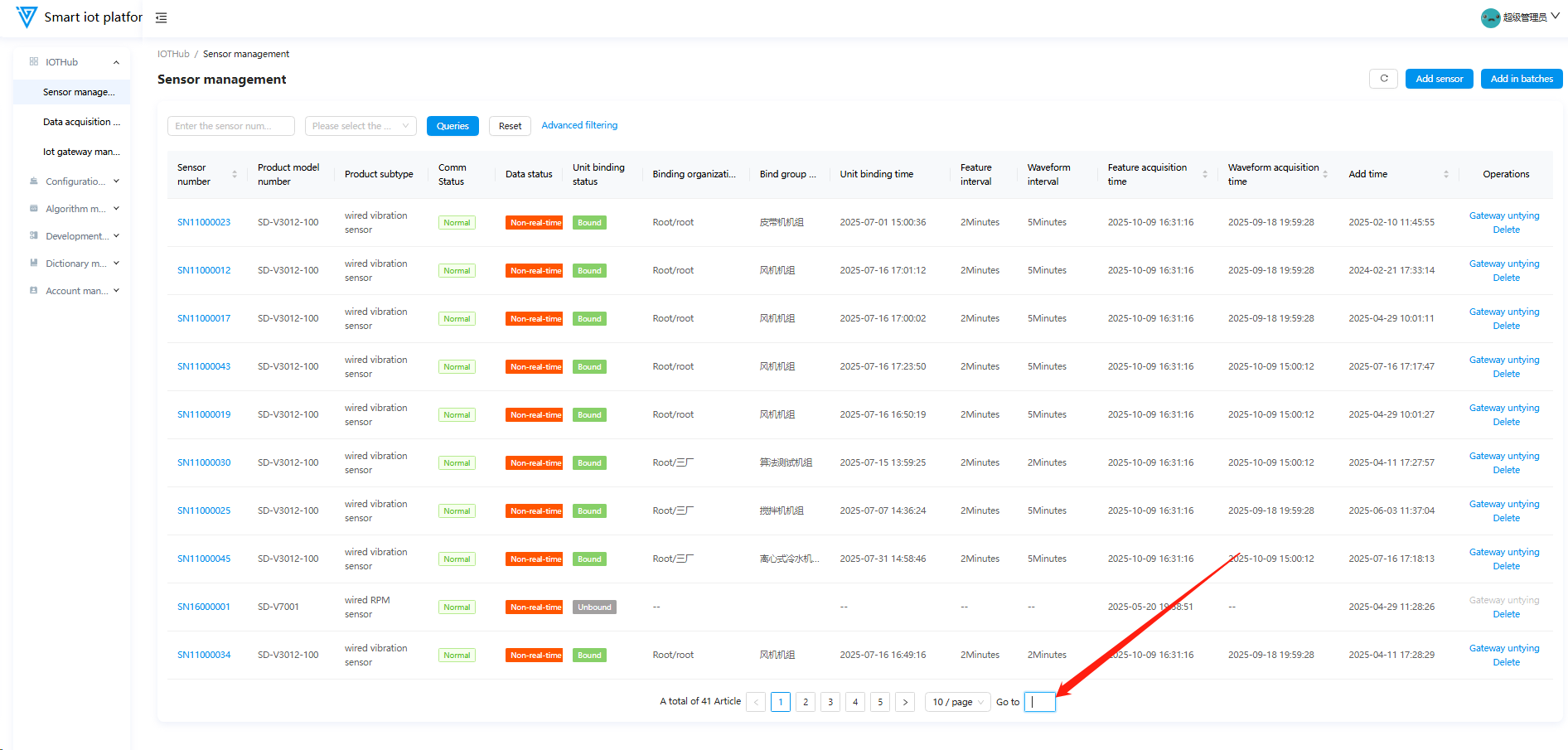
1.2 Page Navigation
-
Click the < > buttons to navigate between pages.
-
Click the target page number to jump directly.
-
Enter the page number in the input field and press Enter to jump.
2. Filter Query
Select or enter filter criteria as prompted, then click Query. Click Reset to clear all criteria.
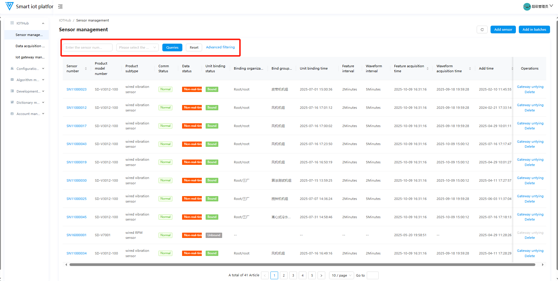
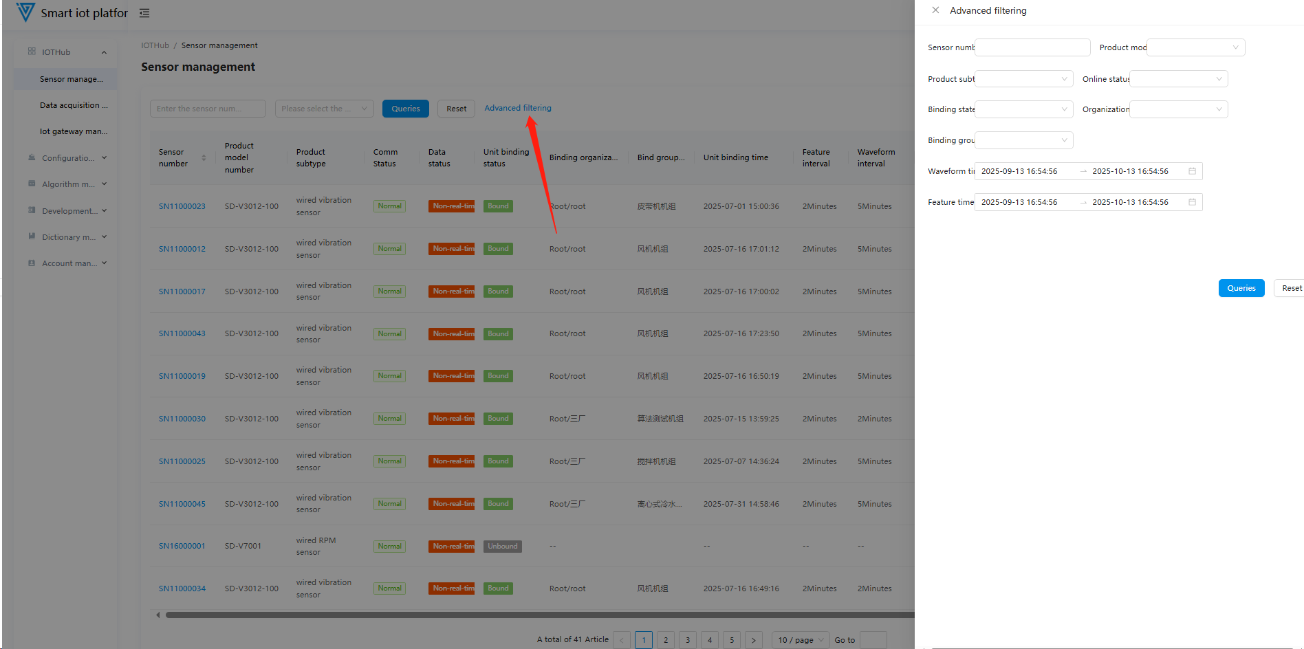
- The Sensor Management page has an exclusive Advanced Filter button. Click to open the sidebar for more filtering conditions (other operations remain the same).
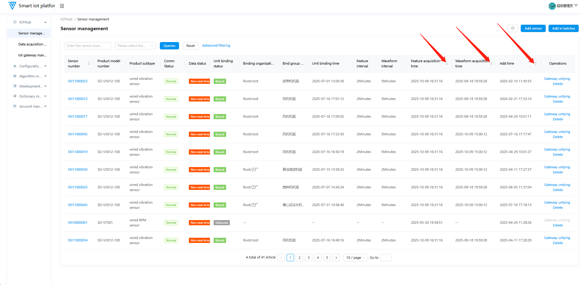
3. Data Sorting
Some data columns support sorting. Click the header to sort in ascending/descending order or cancel sorting.
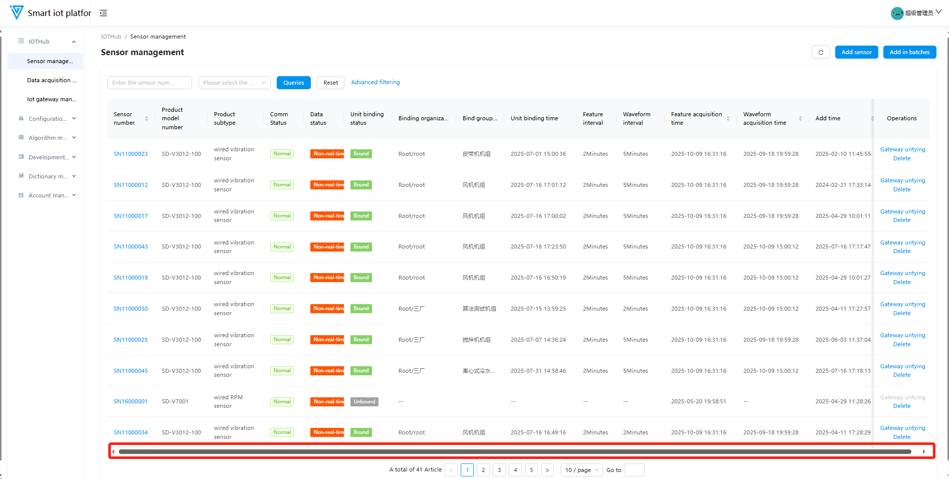
4. Page Layout
On pages with excessive data columns, use the horizontal scroll bar below to view all content.
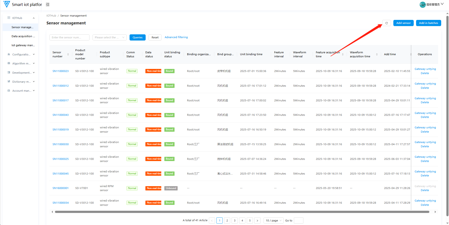
5. Data Refresh
Click Refresh to force an update of the page content.
IOTHub
1. Sensor Management (Home Page)
1.1 Function Overview
Operations personnel can use this function to add, delete, edit, and configure wired/wireless sensors.
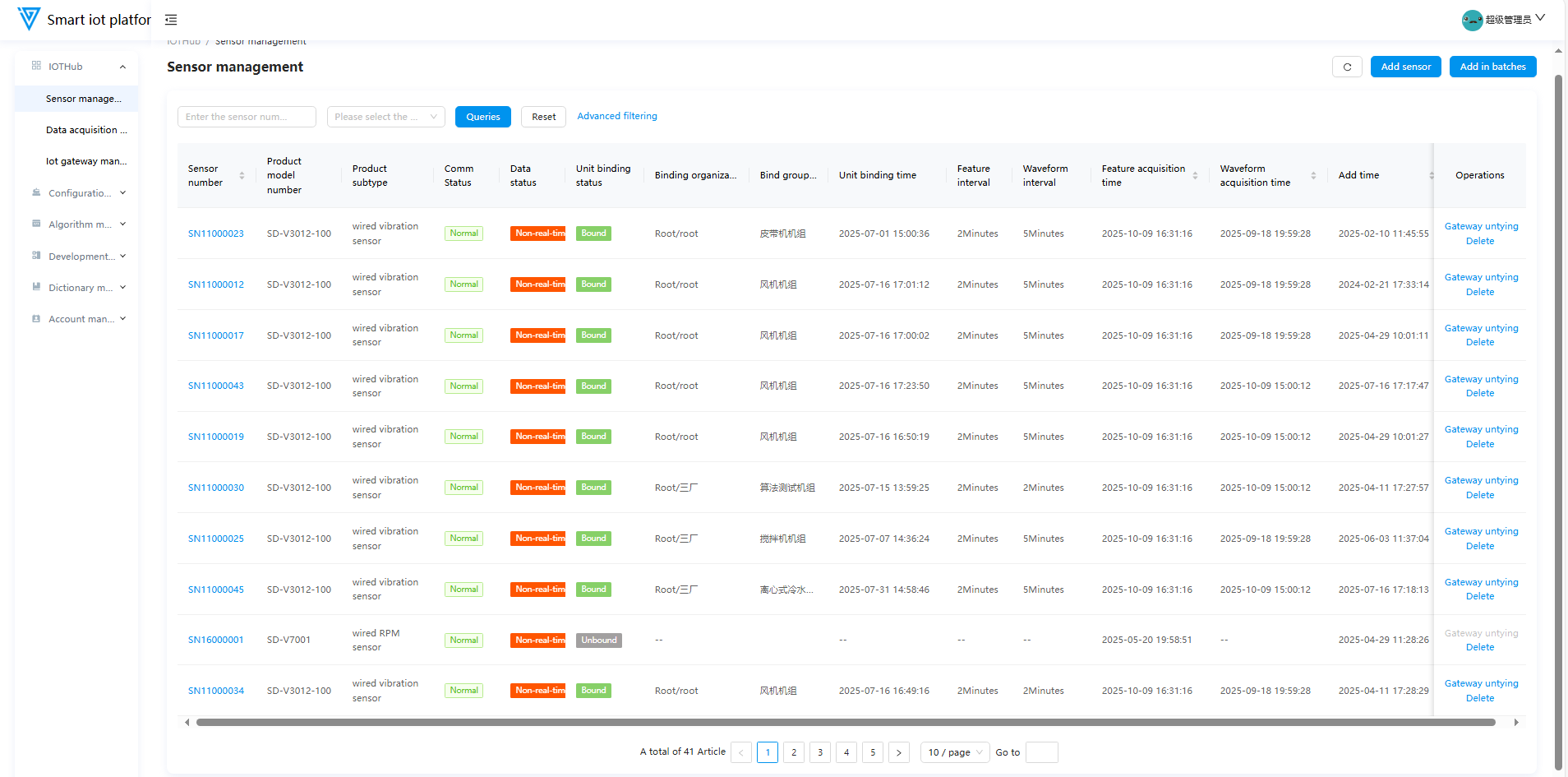
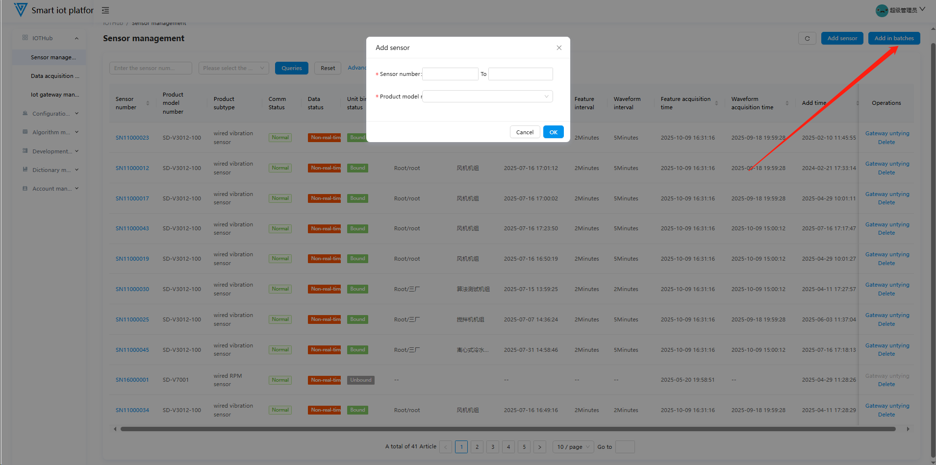
1.2 Adding Sensors
Click Add Sensor or Batch Add in the upper-right corner of the Sensor Management page. Fill in the number information according to the rules, select the product model, and click OK to add.
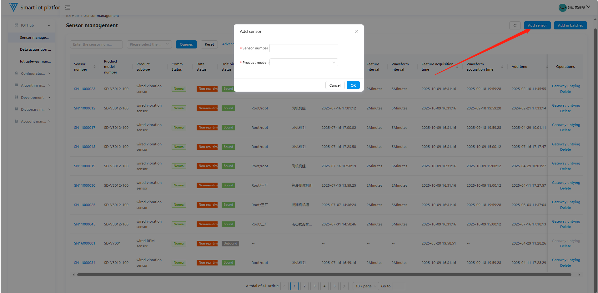
- Sensor Numbering Rules: Starts with SN, 10 digits total. The middle 2 digits indicate the monitoring type, and the last 6 digits are a unique serial number.
| Product Model | Number Format | Product Type | Characteristics |
| ------------------- | ----------------- | --------------------------------------- | --------------------- |
| SD-V3012-100 | SN11XXXXXX | Single-axis wired acceleration sensor | 100mg |
| SD-V3012-500 | SN11XXXXXX | Single-axis wired acceleration sensor | 500mg |
| SD-V3207-ZG | SN12XXXXXX | Three-axis wireless ZigBee sensor | 10k |
| SD-V3207-4G | SN13XXXXXX | Three-axis wireless 4G-cat1 sensor | 10k, 4G-cat1 |
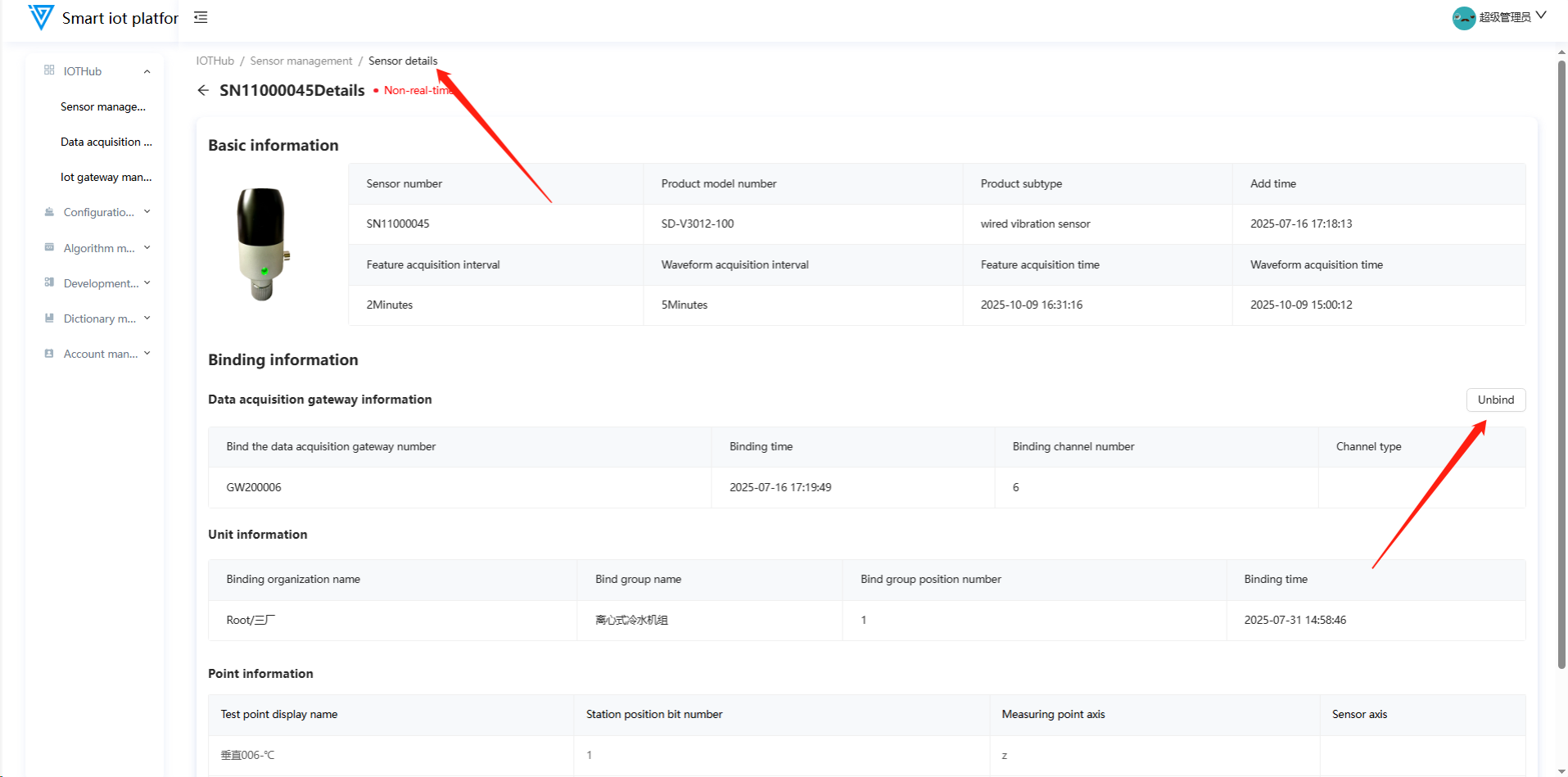
1.3 Sensor Gateway Unbinding
Unbind the gateway via the sensor list page or sensor details page before deleting a bound sensor.
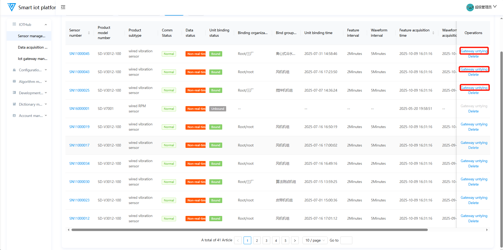
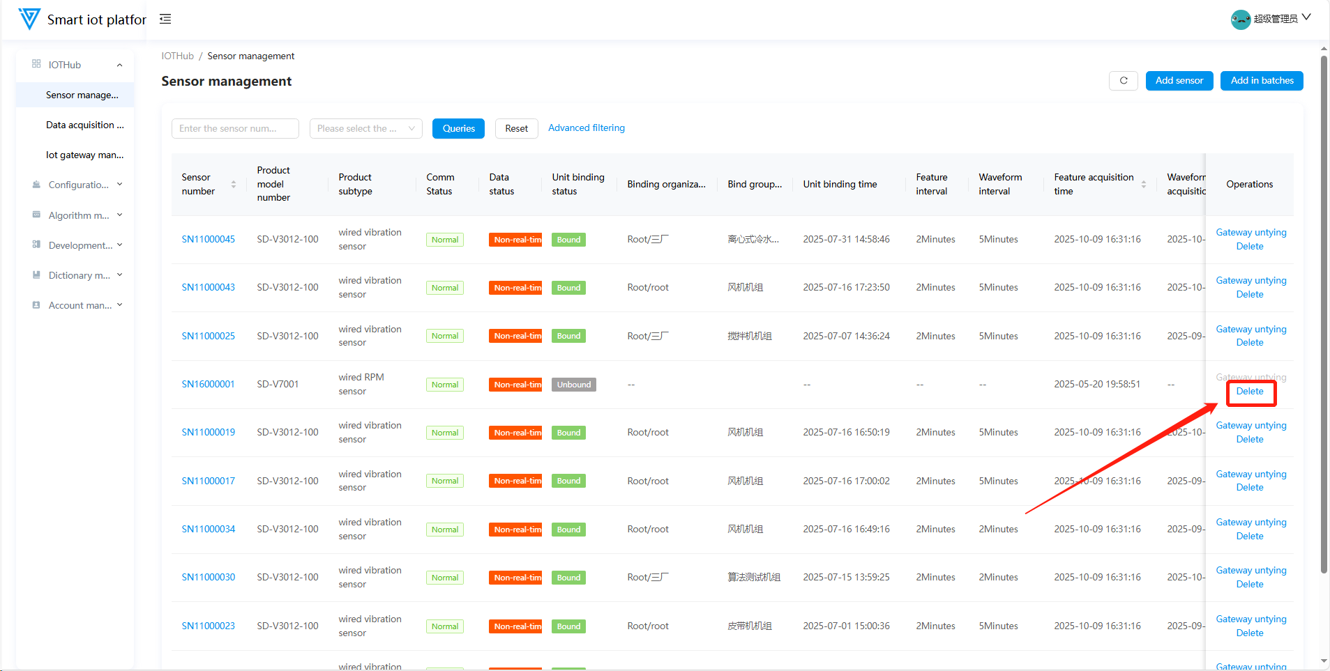
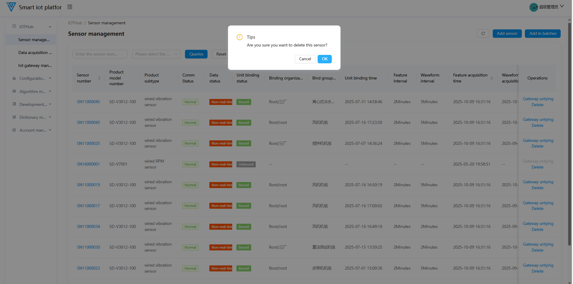
1.4 Deleting Sensors
- Sensors not bound to a gateway can be deleted directly (the Gateway Unbind button is disabled).
- Bound sensors must be unbound from the gateway before deletion.
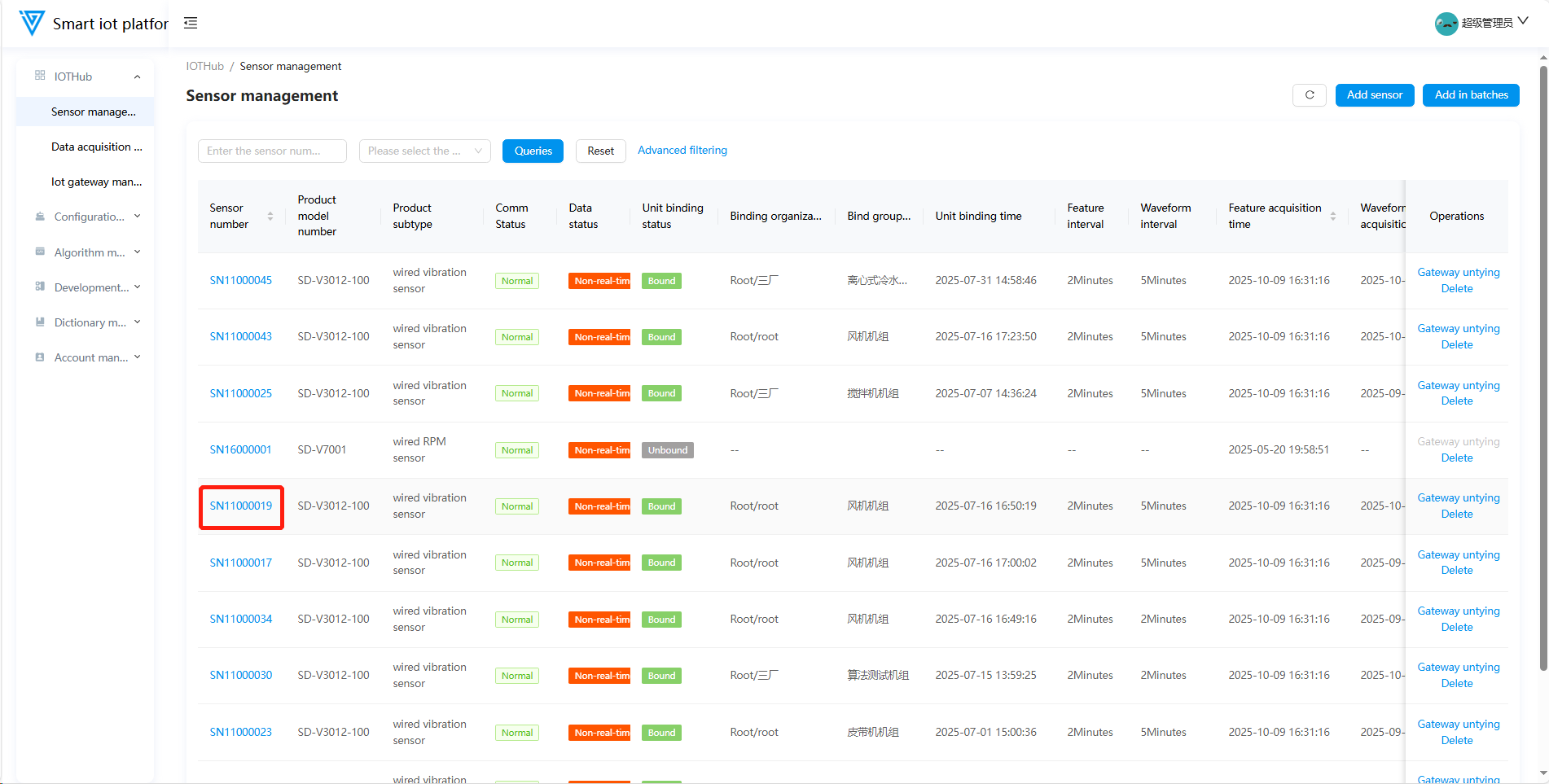
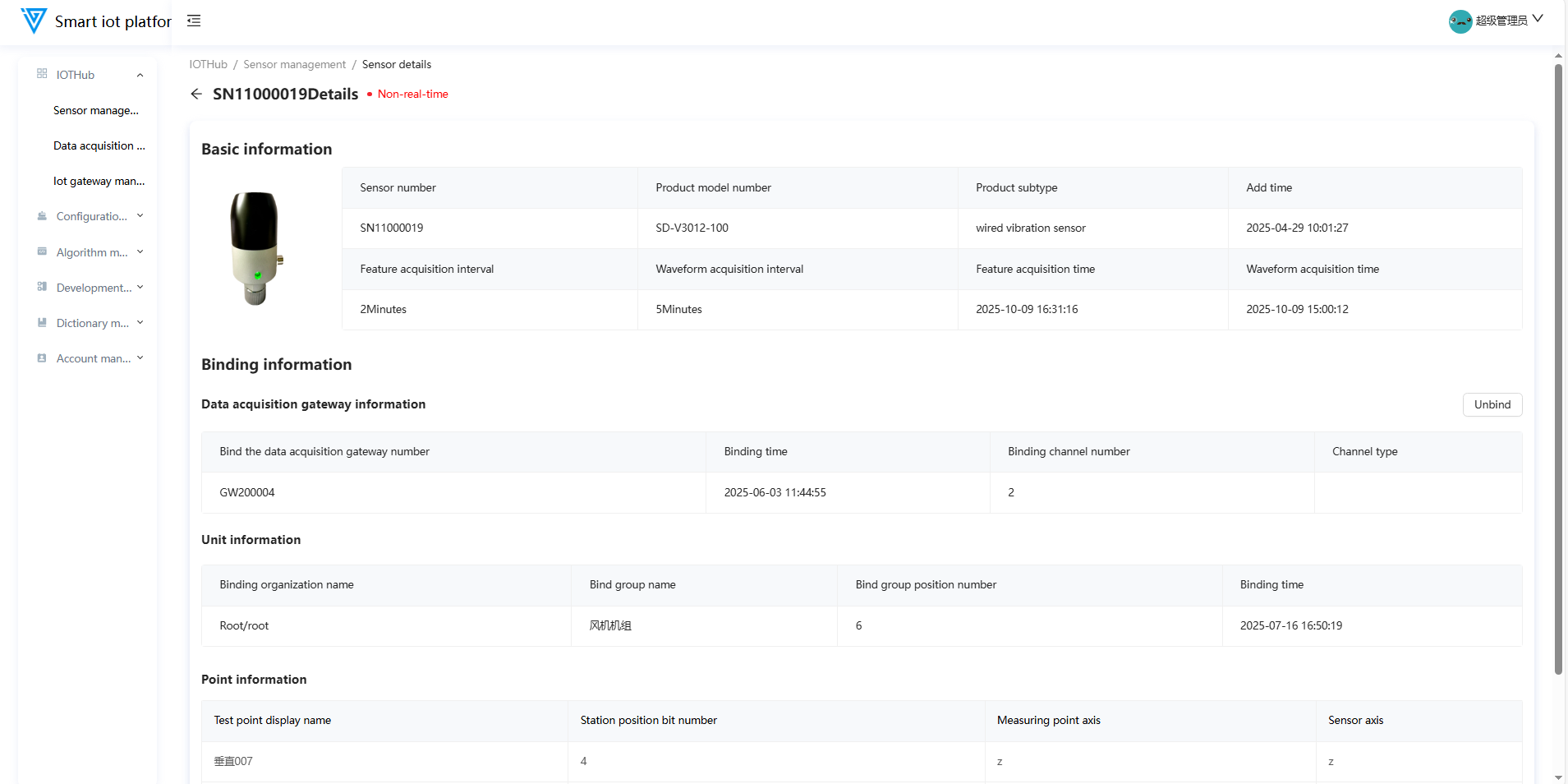
1.5 Sensor Details
Click Details in the sensor list to view transmission status, basic information, and binding details.
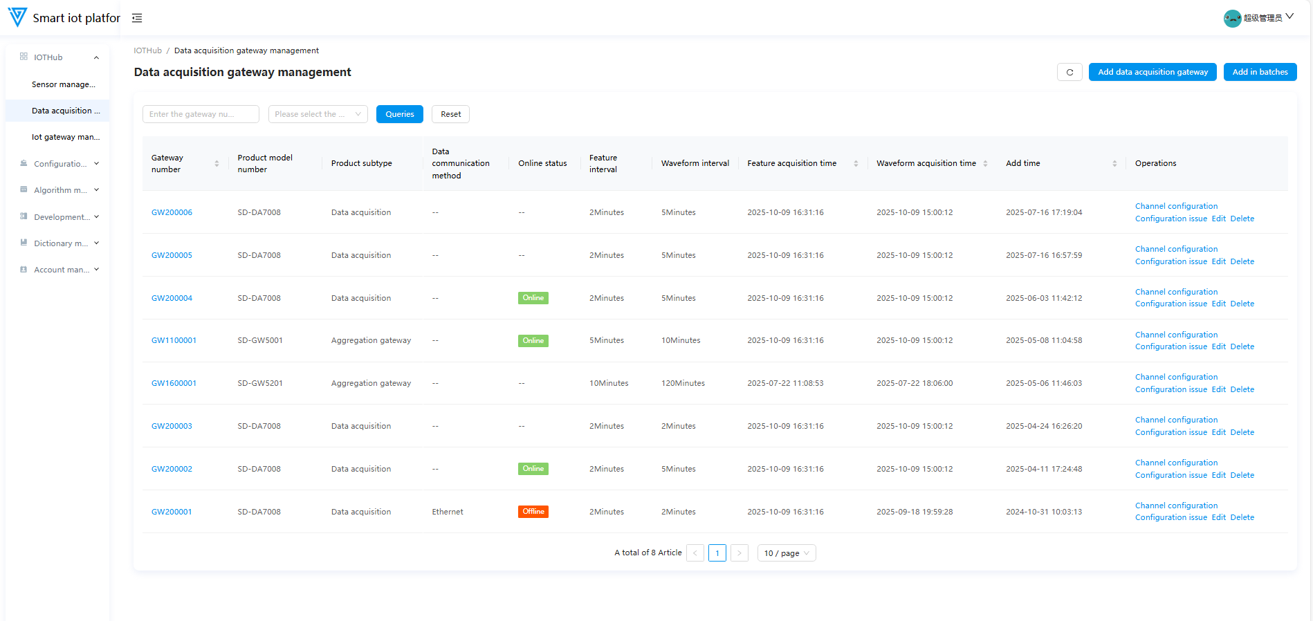
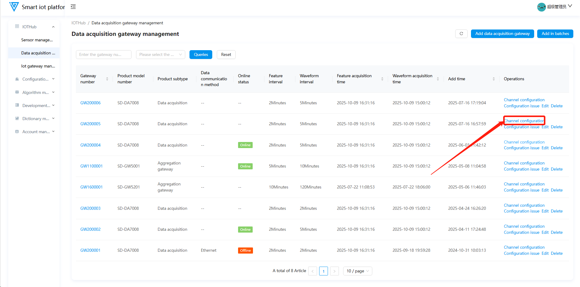
2. Data Acquisition Gateway Management
2.1 Function Overview
Operations personnel can use this function to add data collectors/gateways, bind sensors, deploy acquisition configurations, edit, and delete.
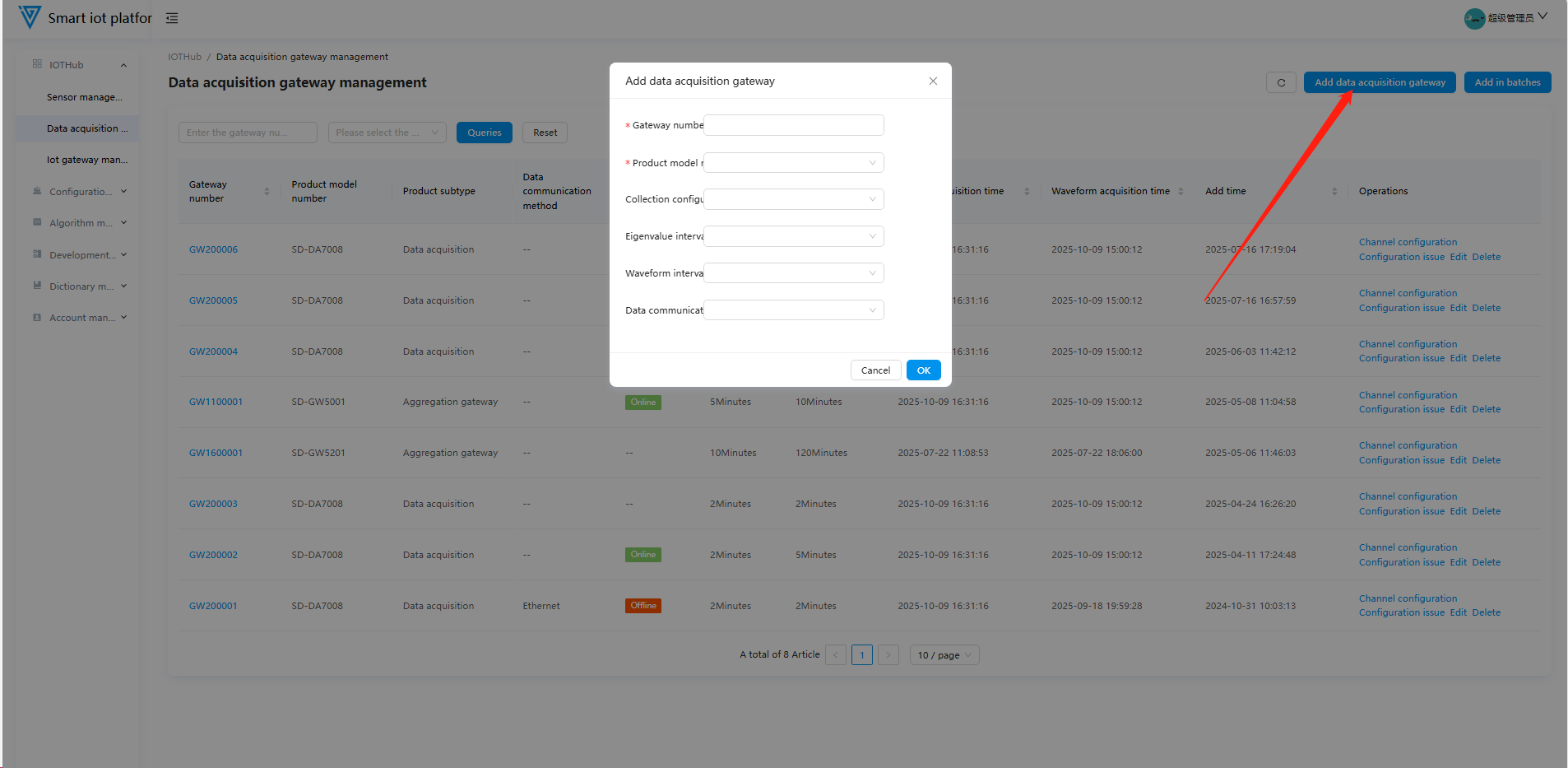
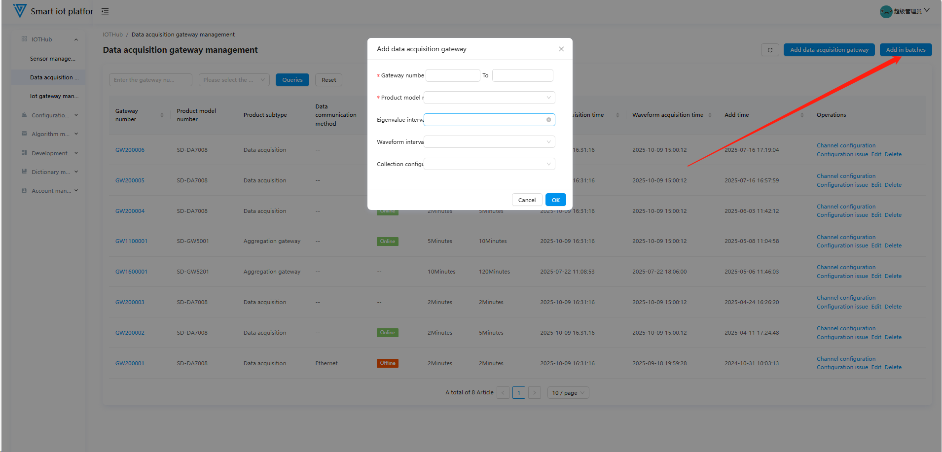
2.2 Adding Data Acquisition Gateways
Click Add Data Acquisition Gateway or Batch Add in the upper-right corner. Fill in Gateway No., Product Model, Acquisition Configuration, Eigenvalue Interval, Waveform Interval, and Data Communication Mode (units for intervals are seconds by default; acquisition configurations must be added in Dictionary Management > Acquisition Configuration).
- Gateway Numbering Rules: Starts with GW, 8 digits total. The first two digits are fixed as GW, the middle digit indicates the gateway type, and the last 5 digits are unique.
| Product Model | Gateway Number Format | Product Type |
| ------------------- | ------------------------------------- | -------------------------- |
| SD-DA7008 | GW2XXXXX | 8-channel vibration collector |
| SD-DA7016 | GW2XXXXX | 16-channel vibration collector |
| SD-DA7024 | GW2XXXXX | 24-channel vibration collector |
| SD-GW5001/5101 | GW11XXXXX-GW15XXXXX | Vibration gateway |
| SD-GW5200/5201 | GW16XXXXX-GW19XXXXX | 4G virtual gateway |
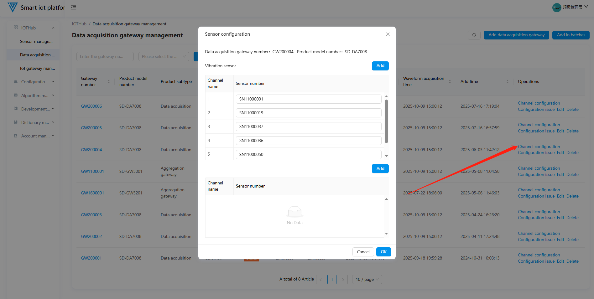
2.3 Gateway Configuration and Deployment
- Click Channel Configuration to bind sensors: enter the sensor number and click OK.
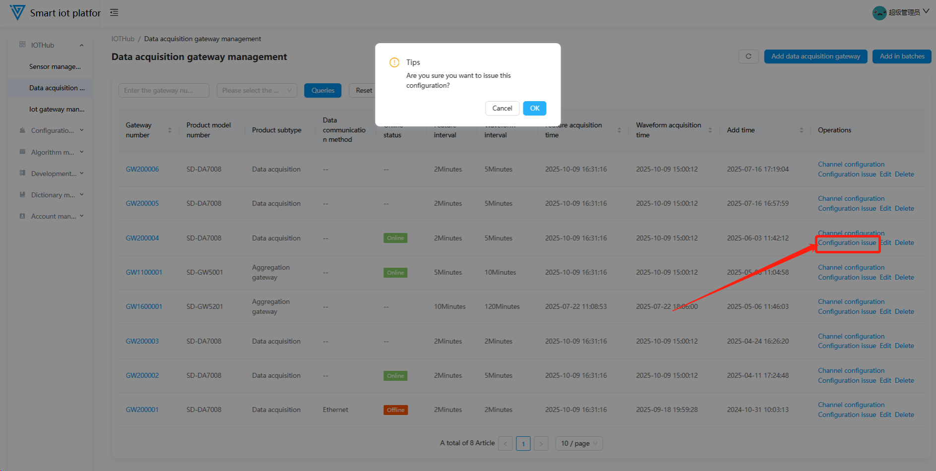
- Click Configuration Deployment to push gateway and sensor information to the data acquisition platform (requires secondary confirmation).
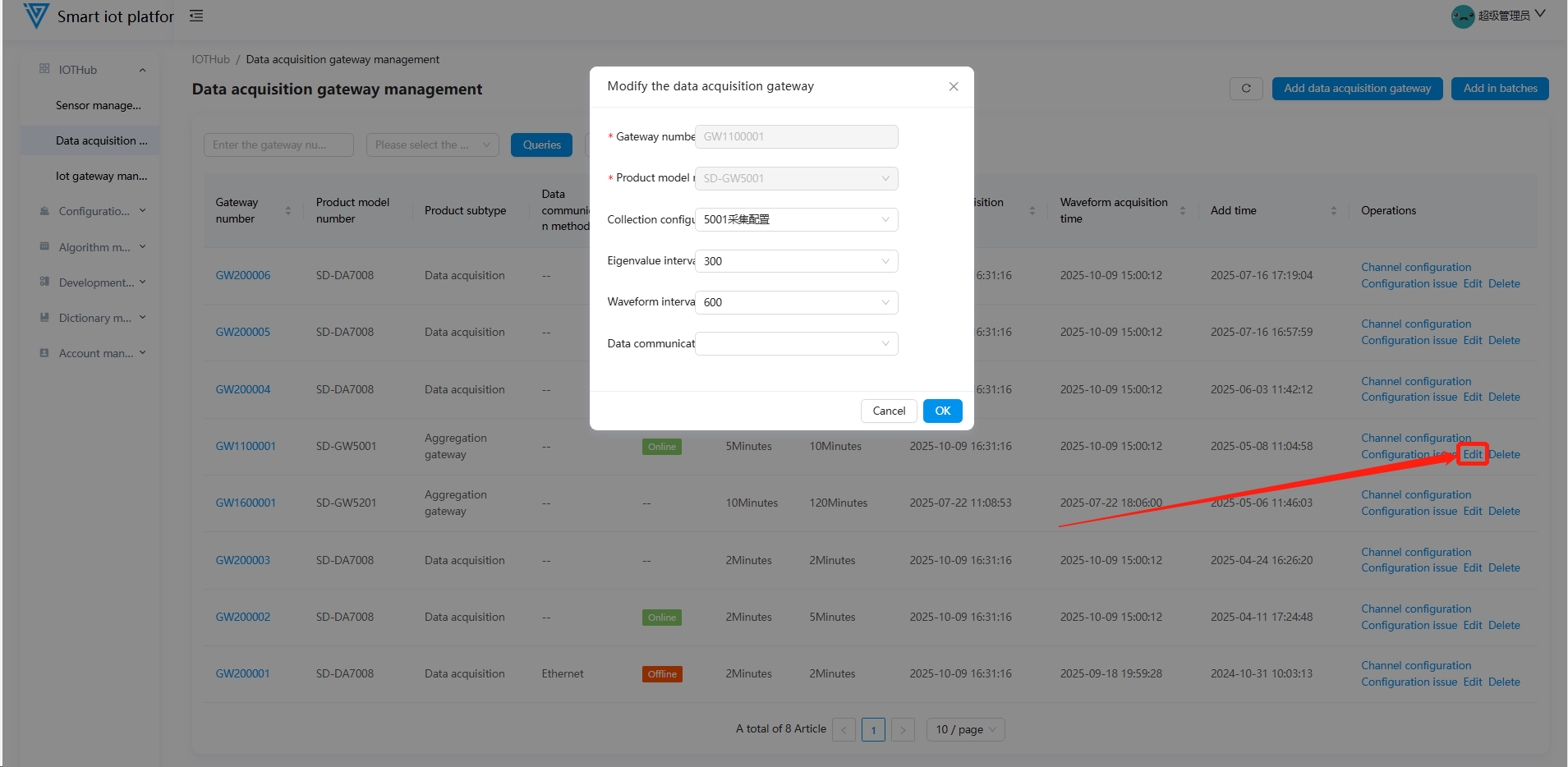
2.4 Editing Gateways
Click Edit to modify gateway information (Gateway No. and Product Model cannot be edited).
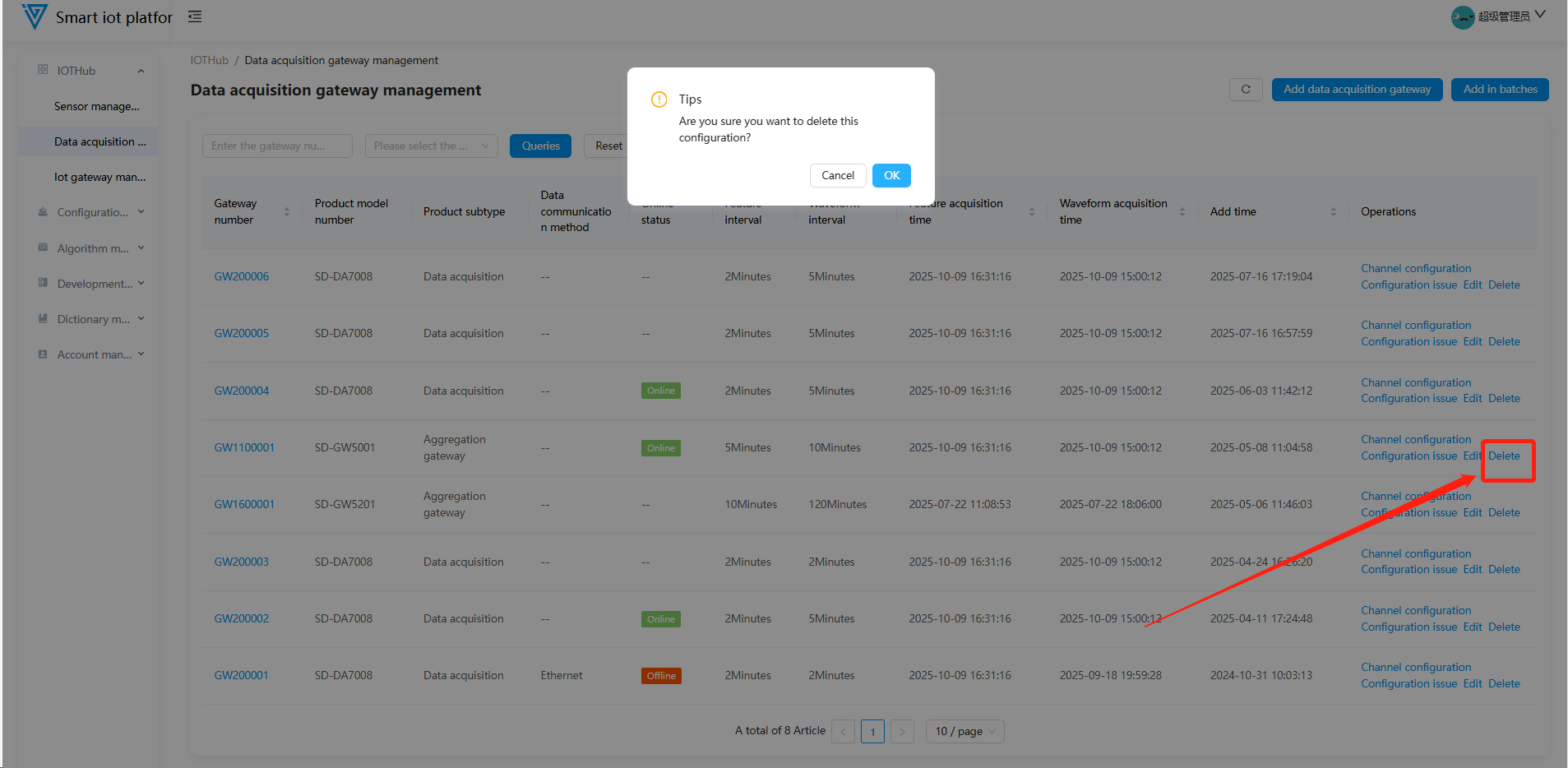
2.5 Deleting Gateways
- Unbind all sensors before deleting a gateway (deletion is disabled for bound gateways).
- Delete directly if no sensors are bound.
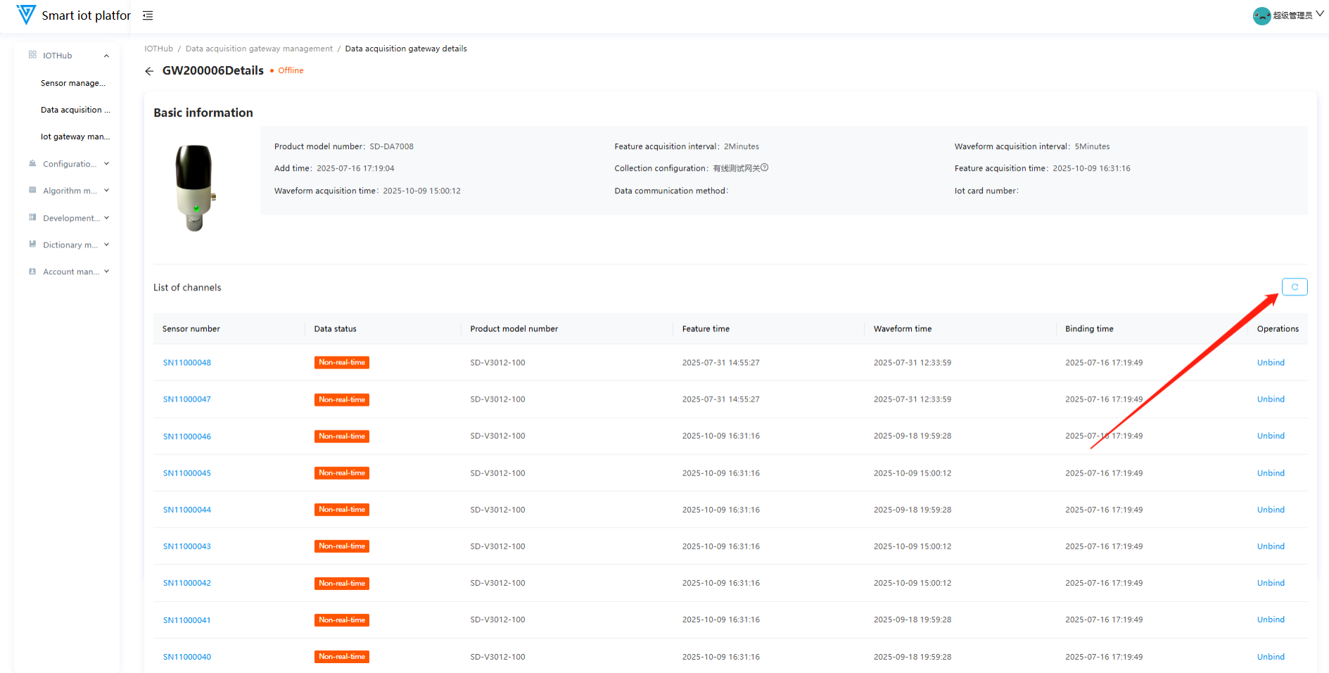
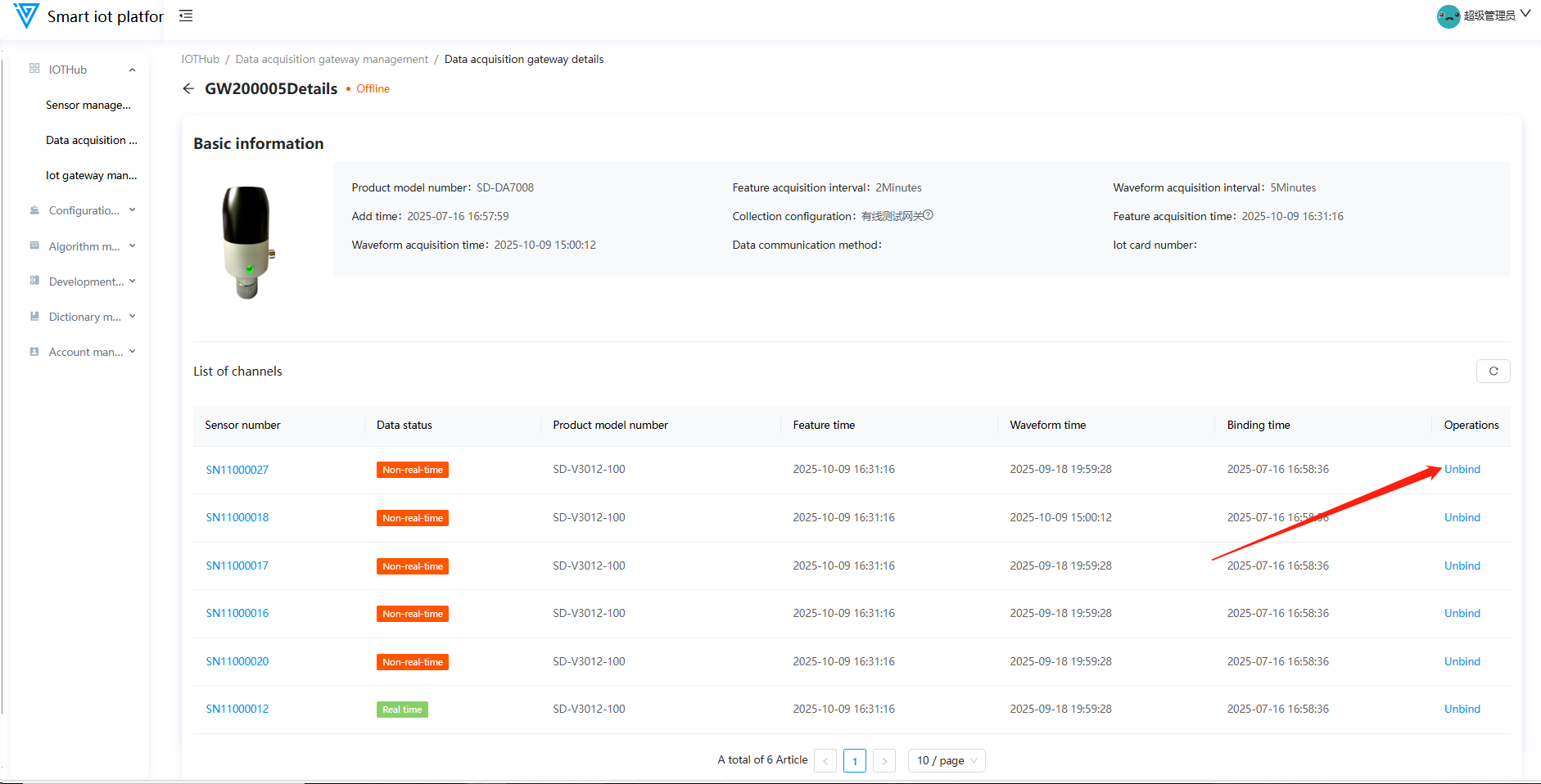
2.6 Gateway Details
Click the gateway number in the list to view basic information and bound sensors (unbind sensors on the details page).

3. IOT Gateway Management
3.1 Function Overview
Operations personnel can use this function to add, edit, configure points, and delete IOT gateways.
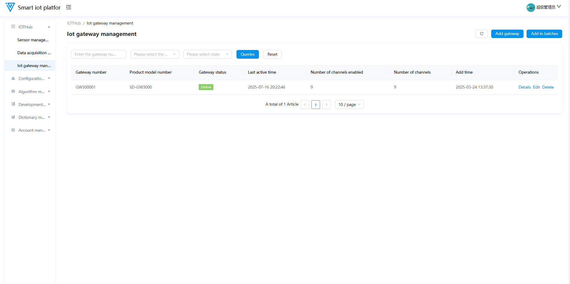
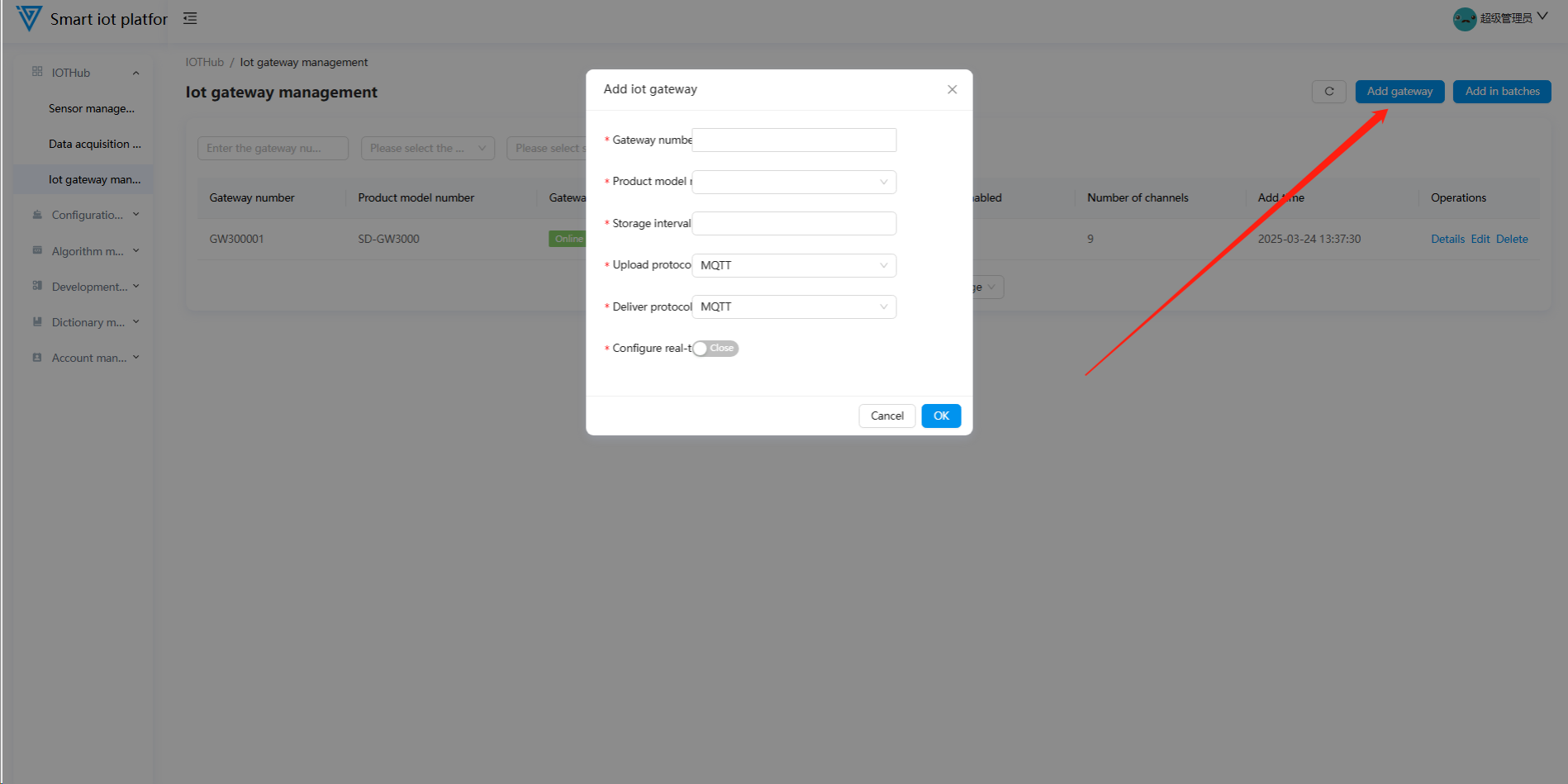
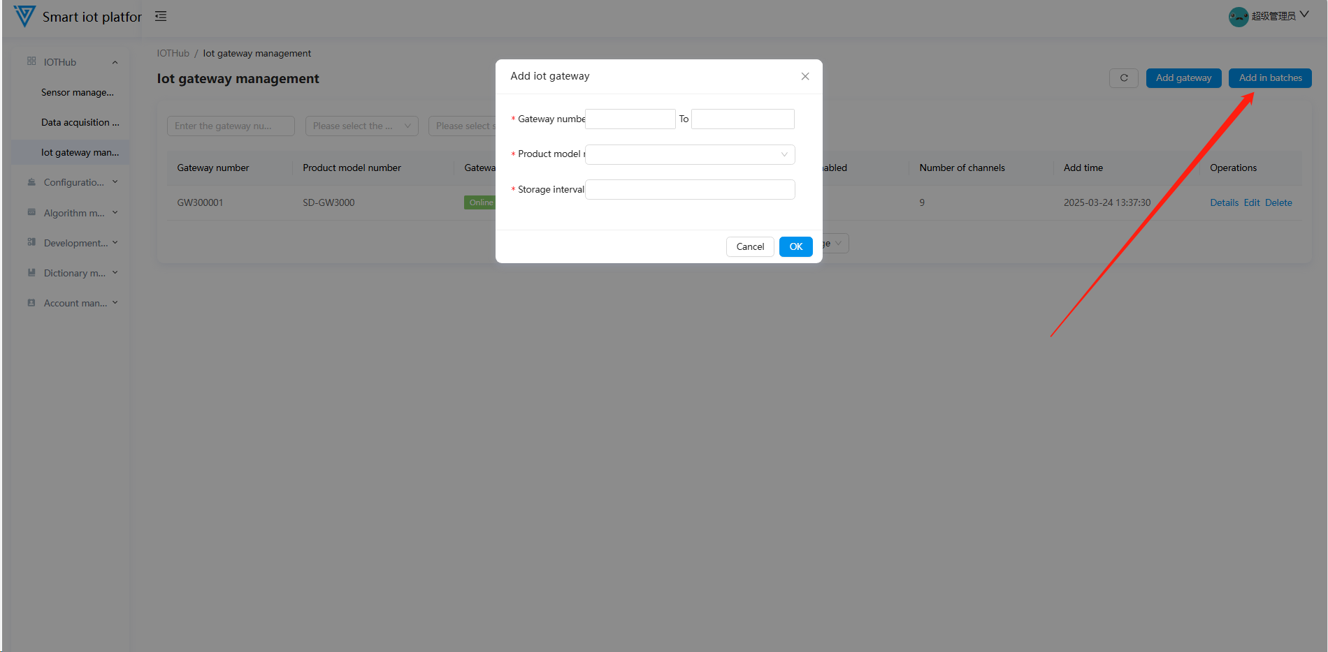
3.2 Adding IOT Gateways
- Current supported product model: SD-GW3000.
- Supported protocols: RMQ, MQTT, OPCUA, API, Page Integration.
- The Configuration Real-time Forwarding switch (disabled by default) determines whether process data is forwarded to the configuration platform.
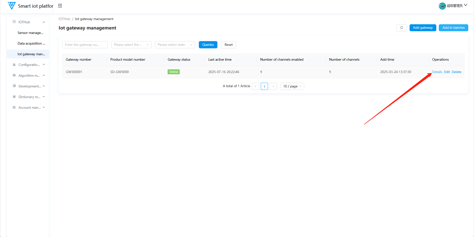
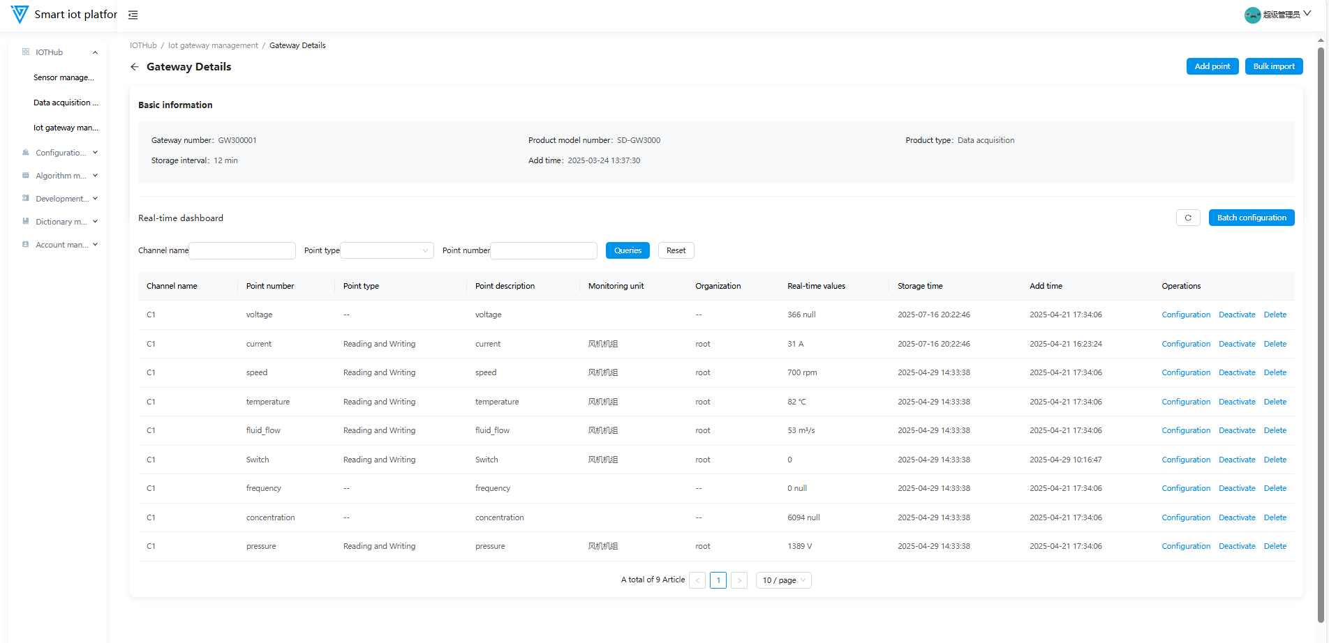
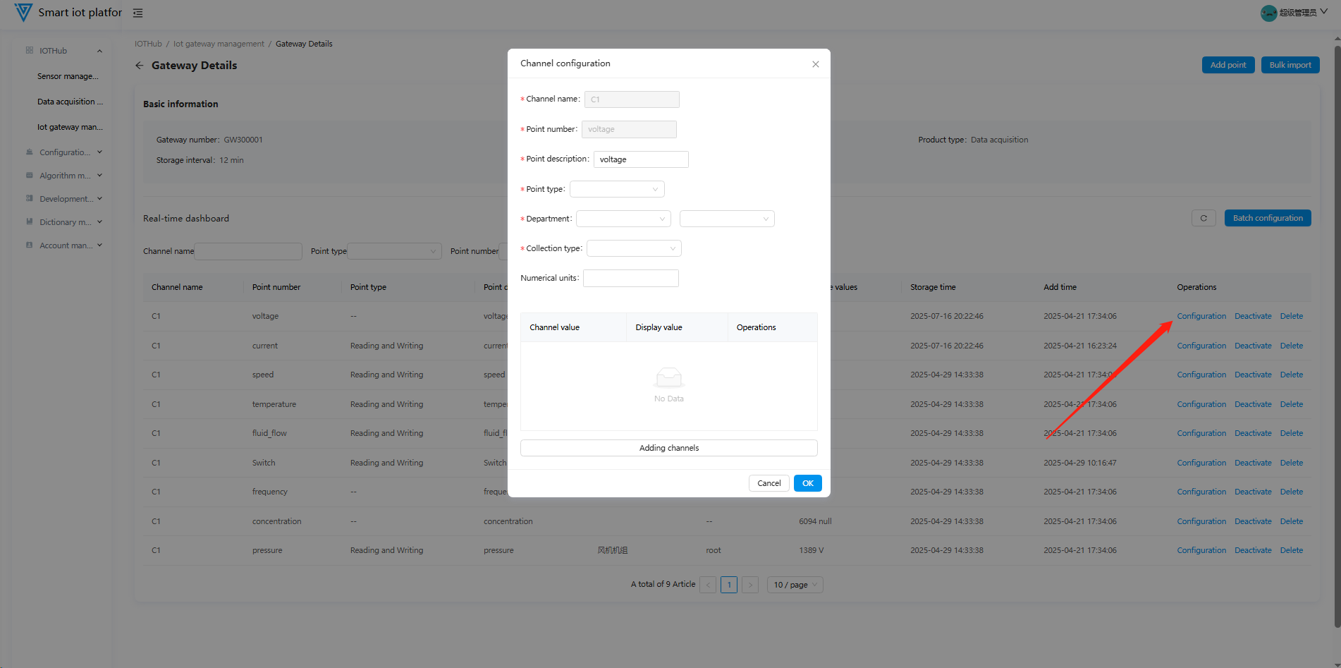
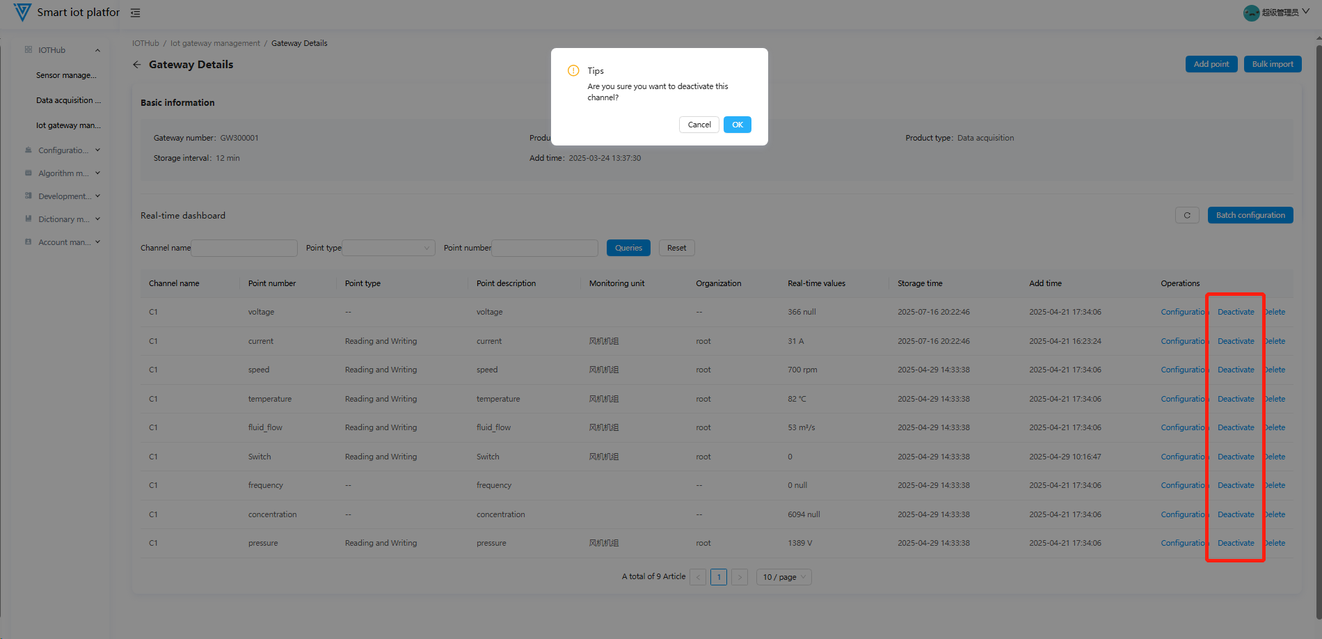
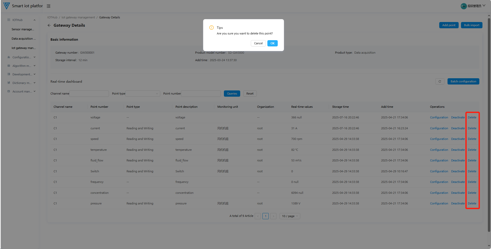
3.3 IOT Gateway Details
Click Details to view basic information and real-time process point dashboards (configure/enable/disable/delete points on this page).
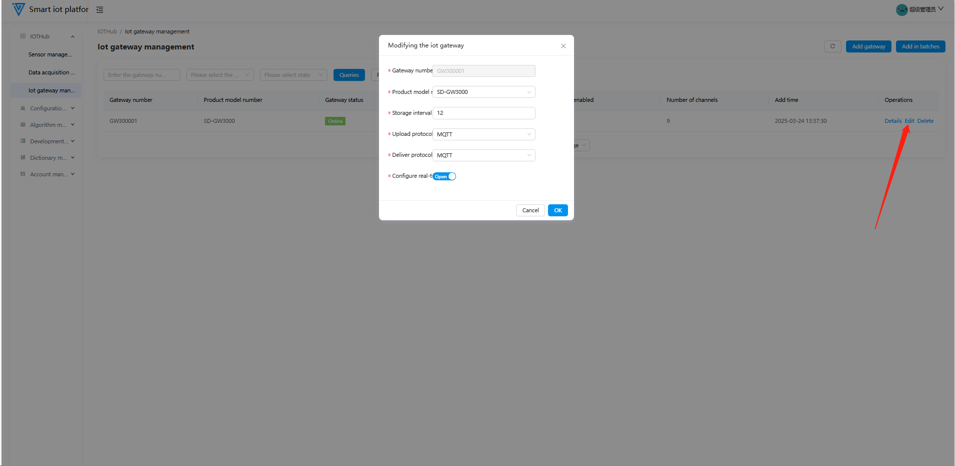
3.4 Editing IOT Gateways
Click Edit in the operation column to modify gateway information.
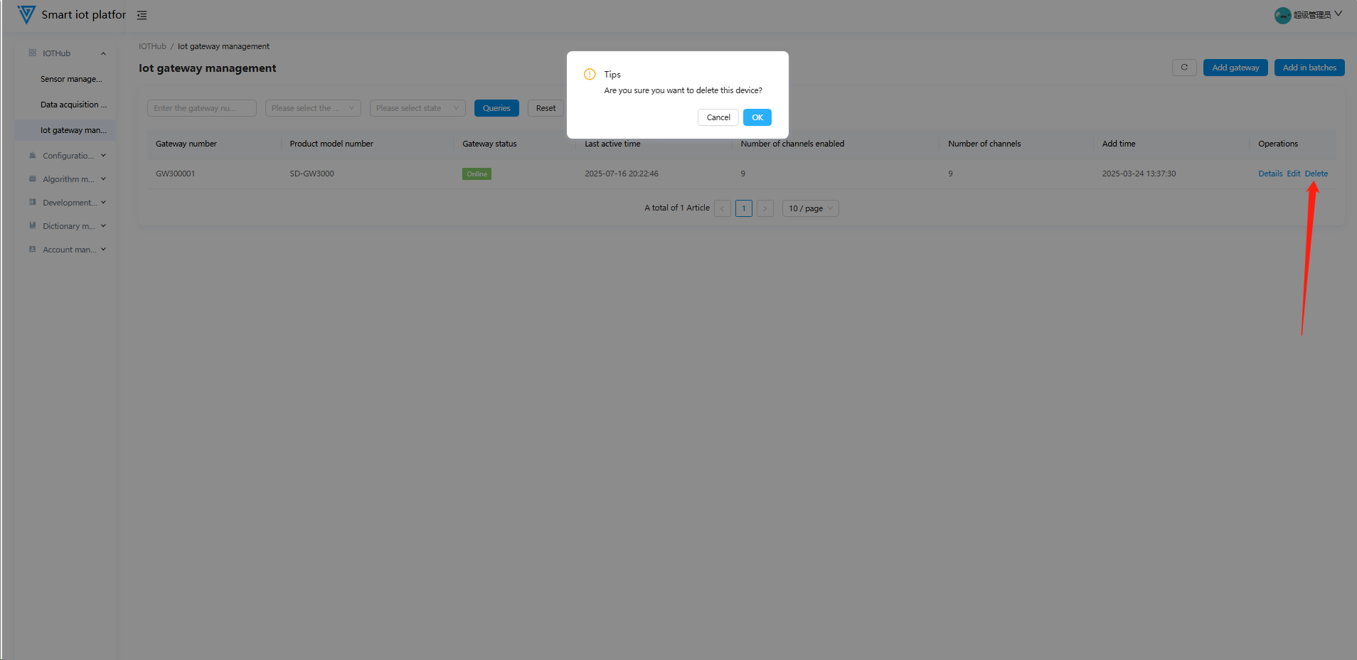
3.5 Deleting IOT Gateways
Unbind all points before deleting. Click Delete in the list (requires secondary confirmation).
Configuration Management
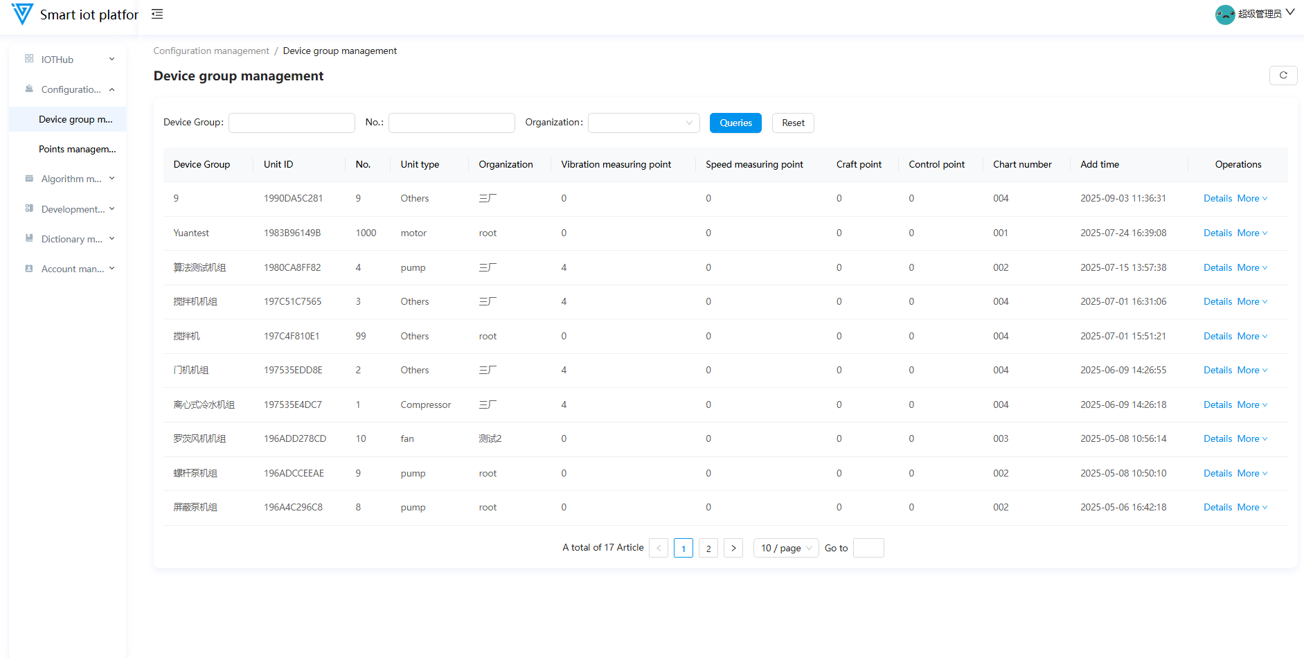
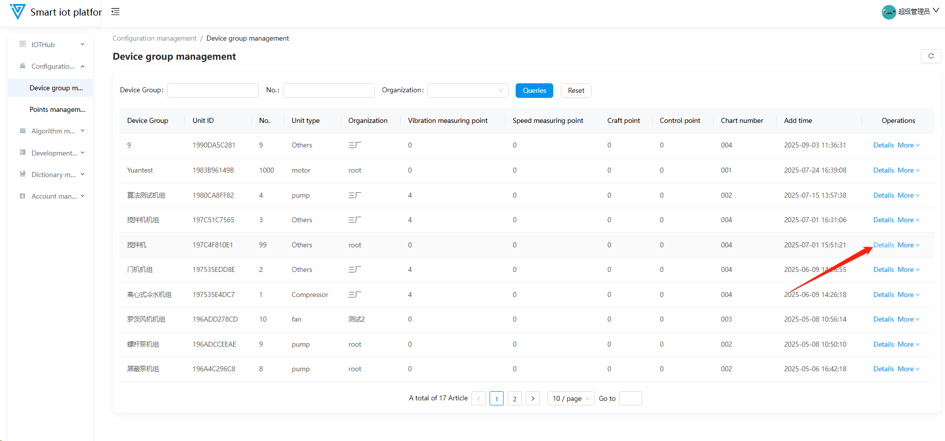
1. Unit Management
1.1 Function Overview
Add/edit/delete units, add measuring points, and view unit details.
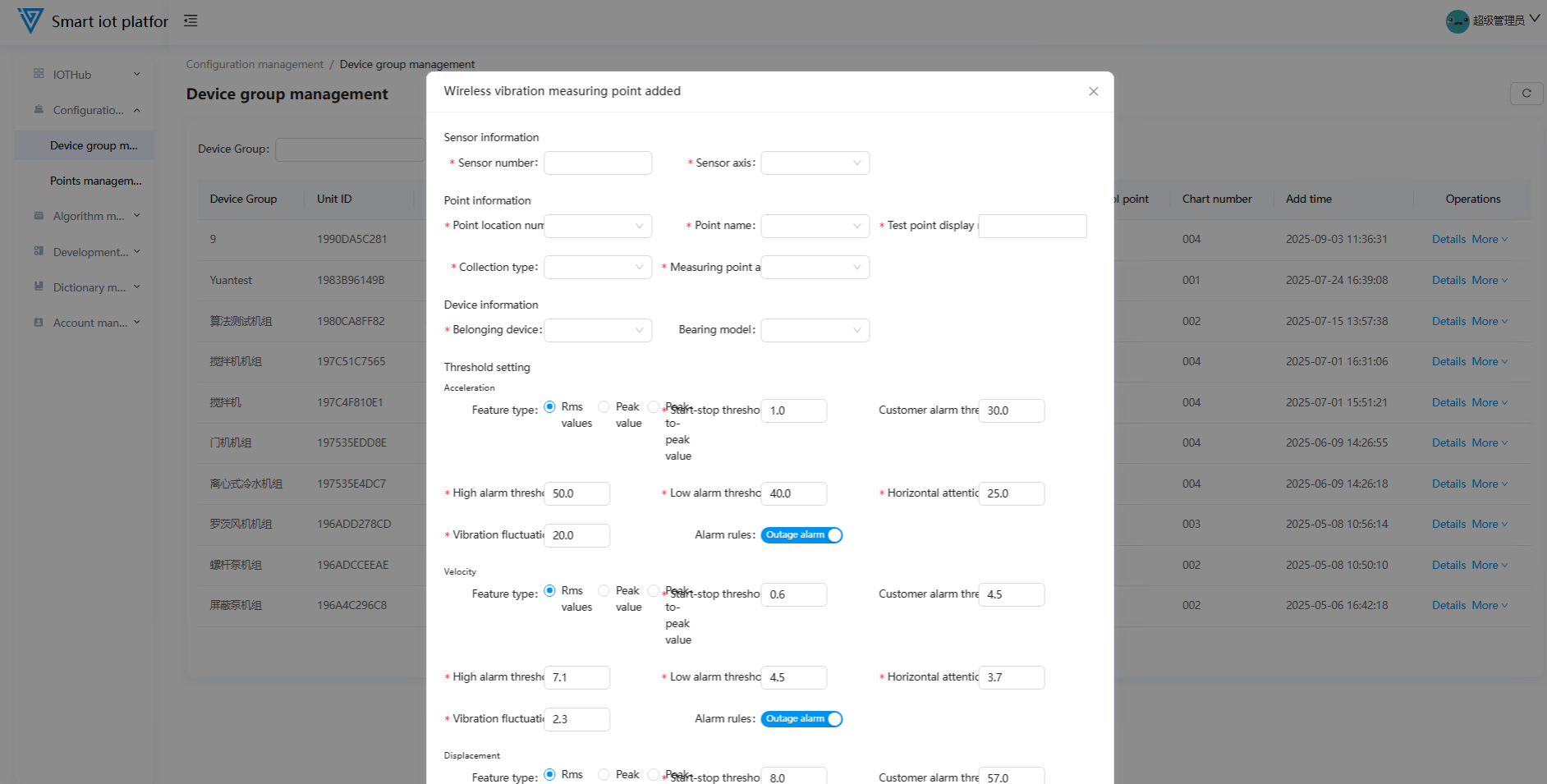
1.2 Adding Wireless Vibration Measuring Points
Click More → Add Wireless Vibration Measuring Point behind the unit, and fill in information in the pop-up window.
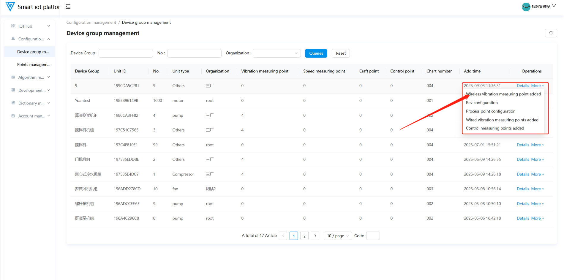
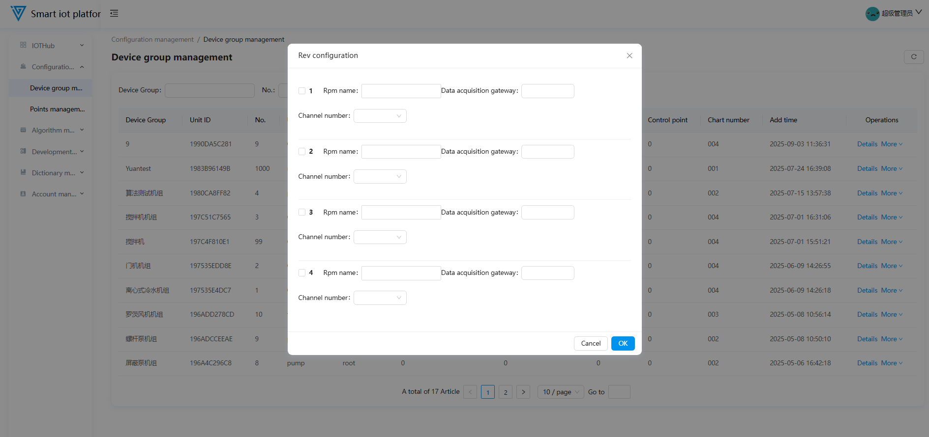
1.3 Speed Configuration
Click More → Speed Configuration behind the unit, and fill in information in the pop-up window.
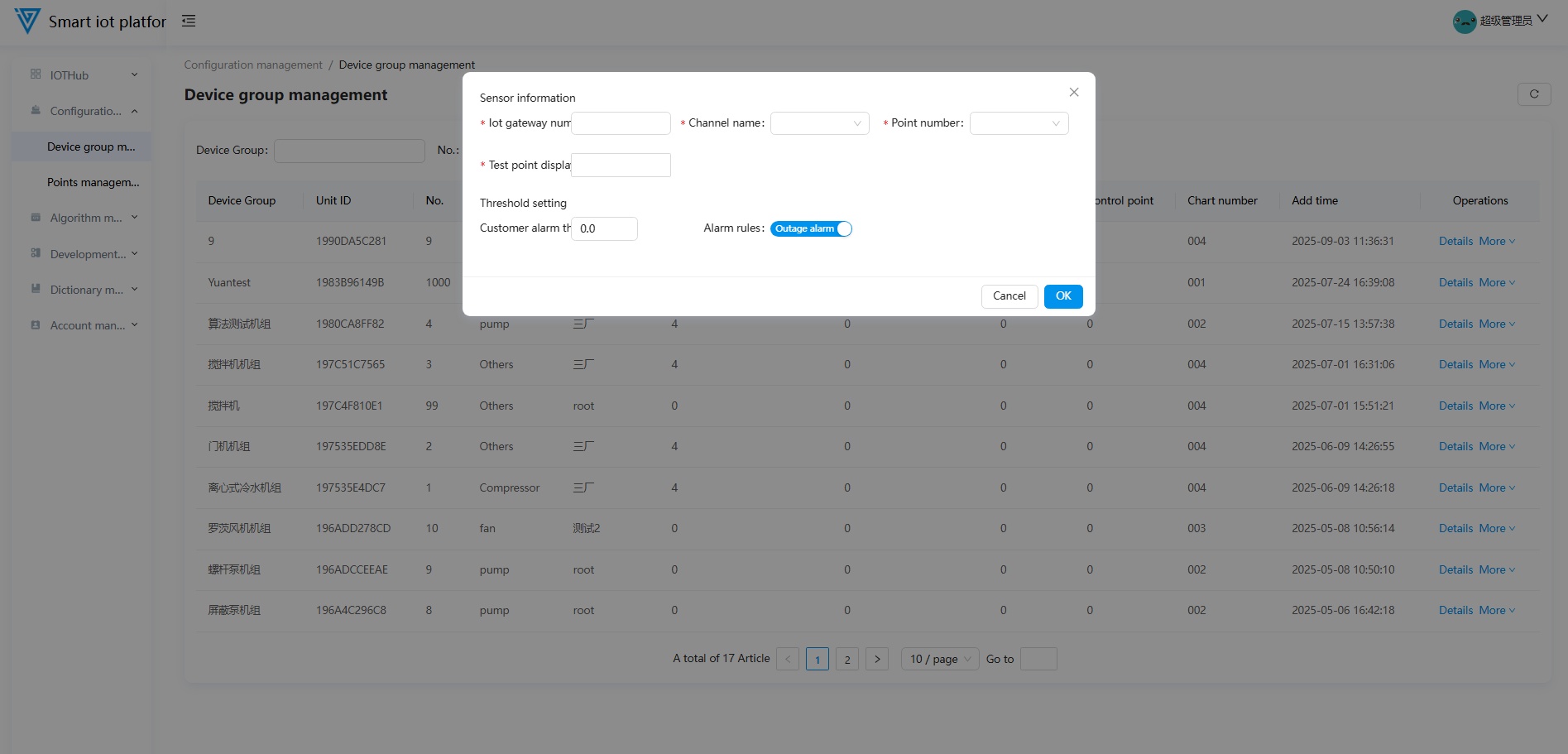
1.4 Process Measuring Point Configuration
Click More → Process Measuring Point Configuration behind the unit, and fill in information in the pop-up window.
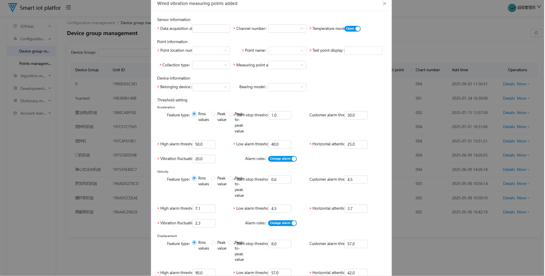
1.5 Adding Wired Vibration Monitoring Points
Click the More button behind the unit and select "Add Wired Vibration Monitoring Point". Fill in the information in the pop-up window to add it.
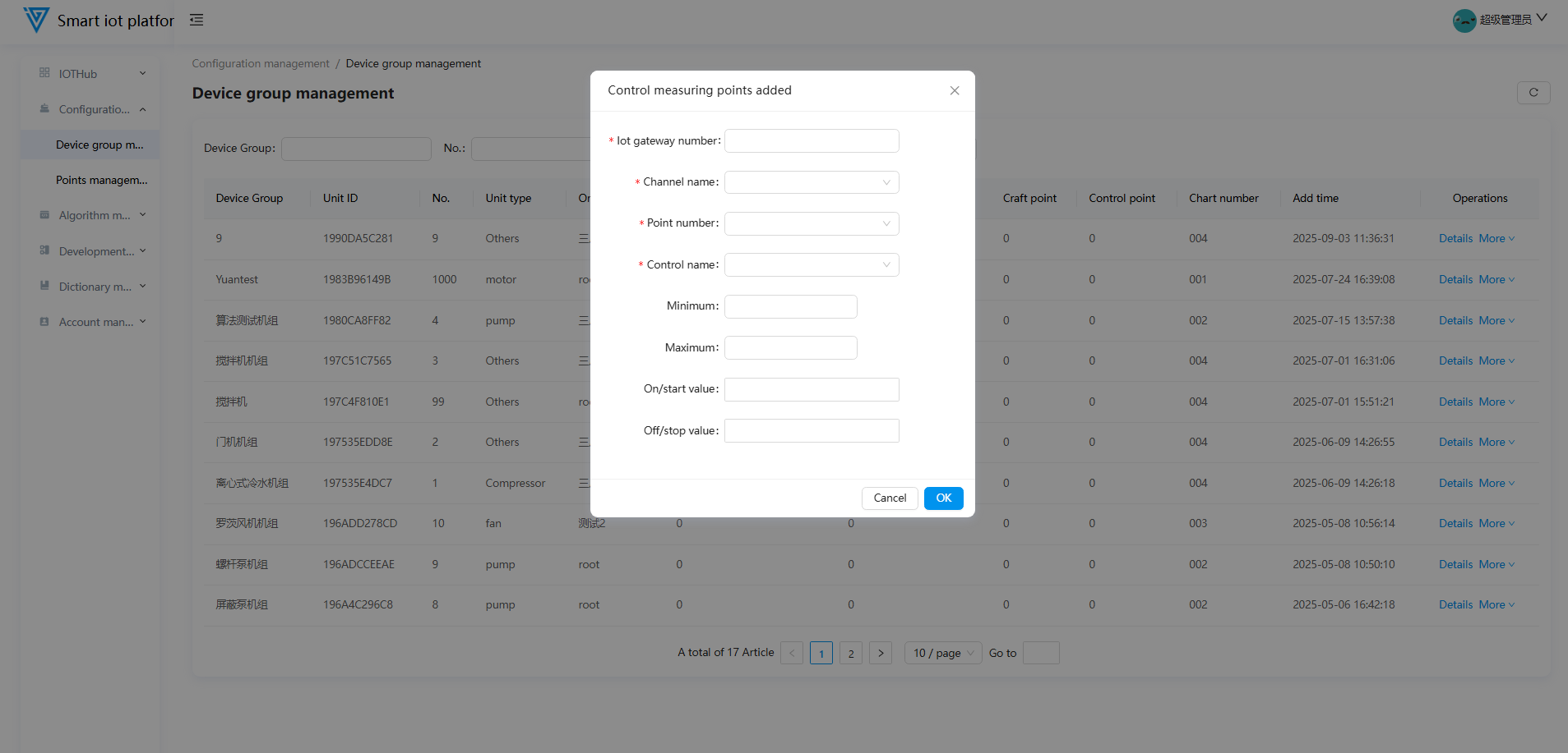
1.6 Adding Control Monitoring Points
Click the More button behind the unit and select "Add Control Monitoring Point". Fill in the information in the pop-up window to add it.
1.7 Unit Details
Click Details behind the unit to enter the details page (configure measuring points, trigger algorithm learning, view parameters, etc.).
-
Click Configure Measuring Points in the upper-right to add wireless vibration/wired vibration/process/control points.
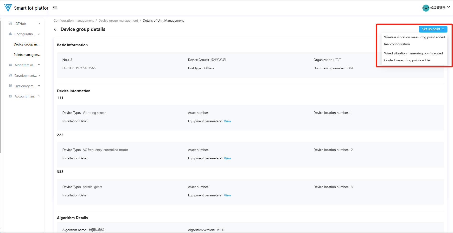
-
Click Learn to trigger manual algorithm learning (click the blue times below to view learning details).
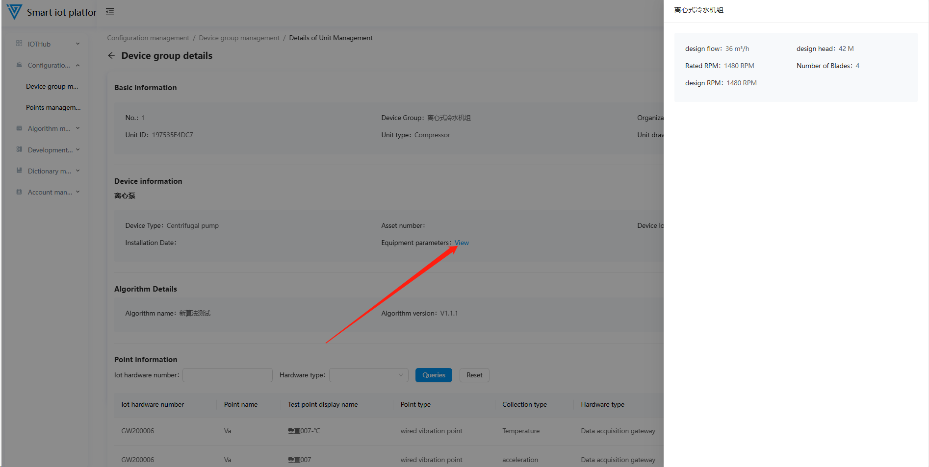
-
Click View (blue text) to view device parameters.
-
View measuring point details below.
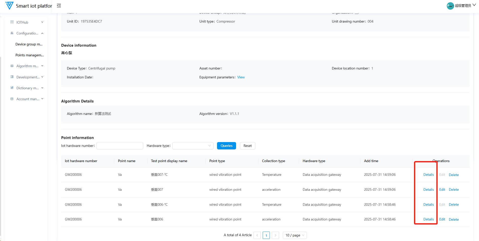
-
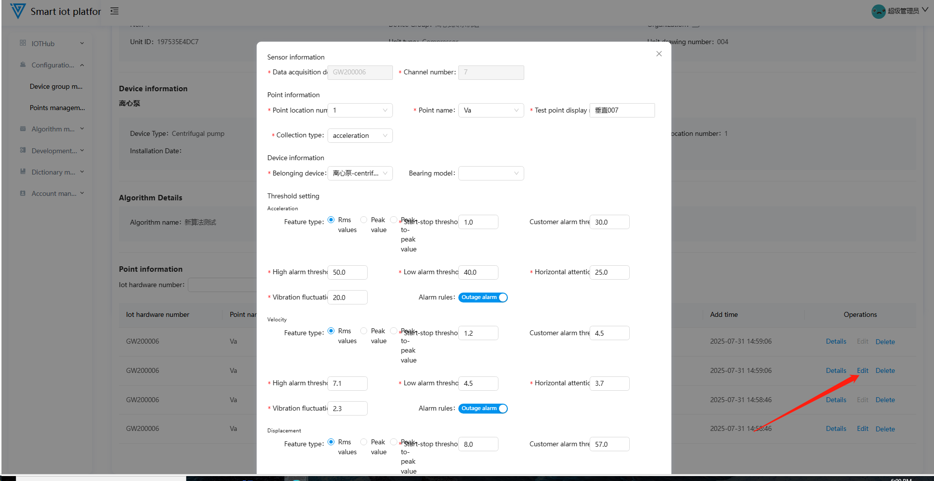
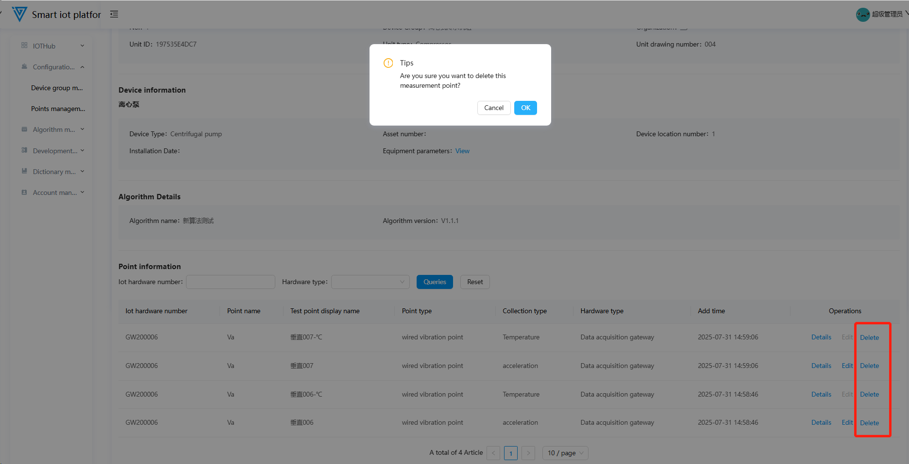
Edit/delete operations:
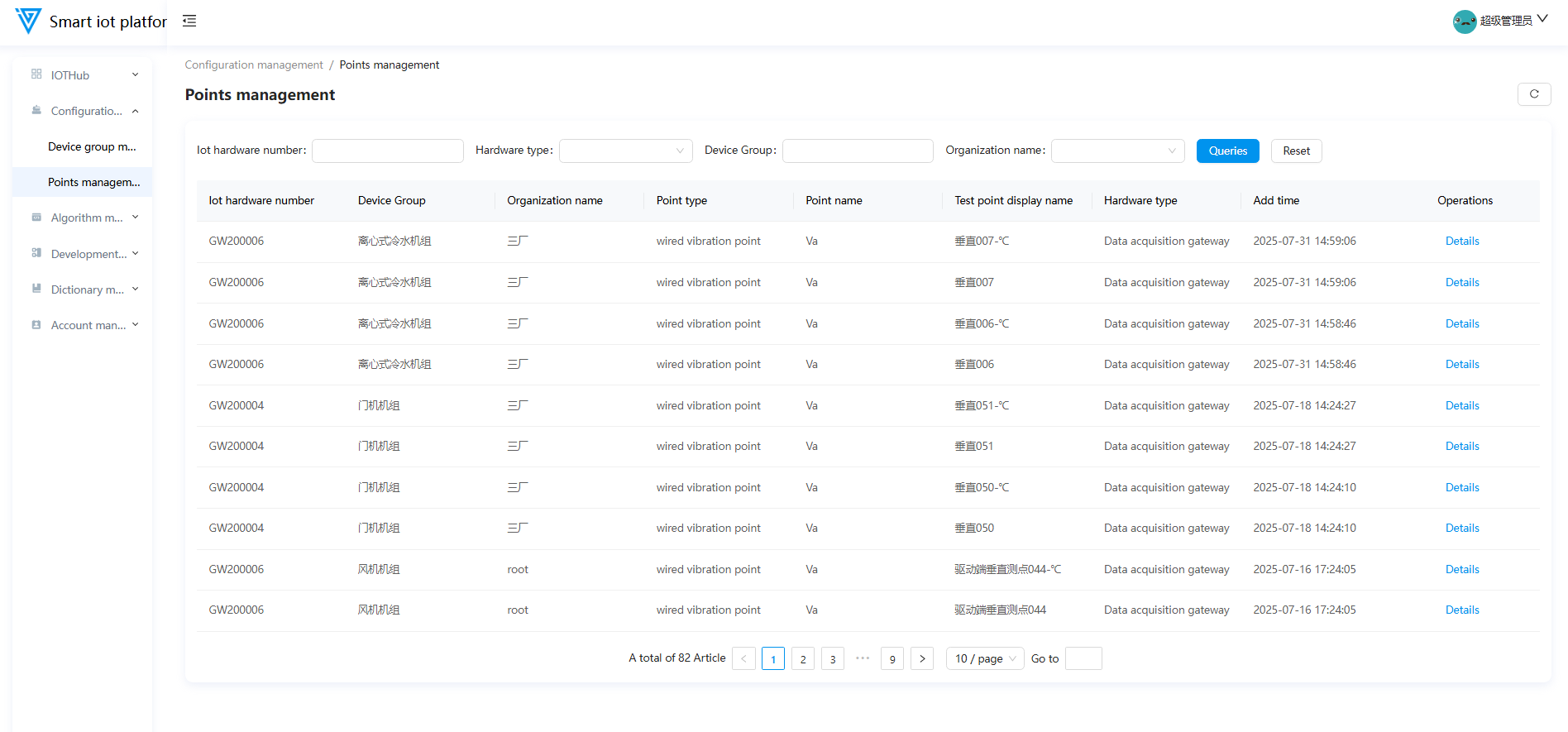
2. Monitoring Point Management
2.1 Function Overview
Centrally manages monitoring point information for IoT devices, providing capabilities for data display, quick search, hierarchical navigation, and operational management.
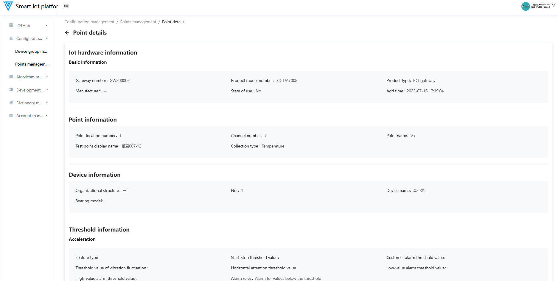
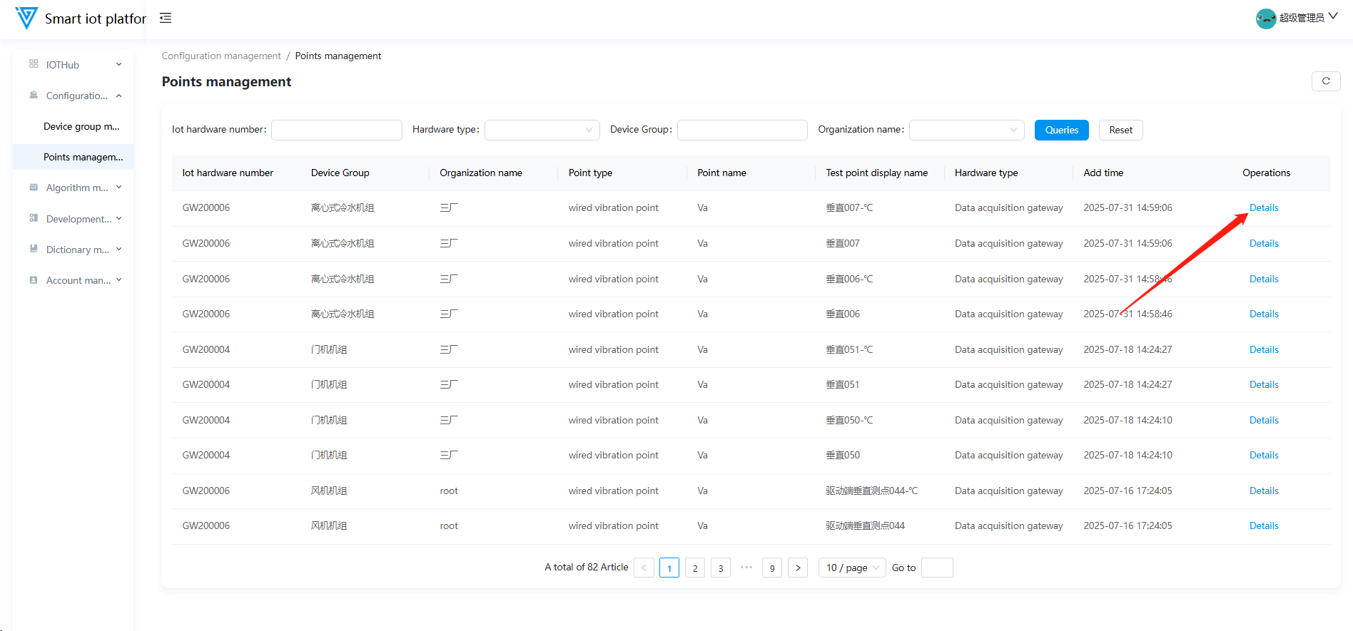
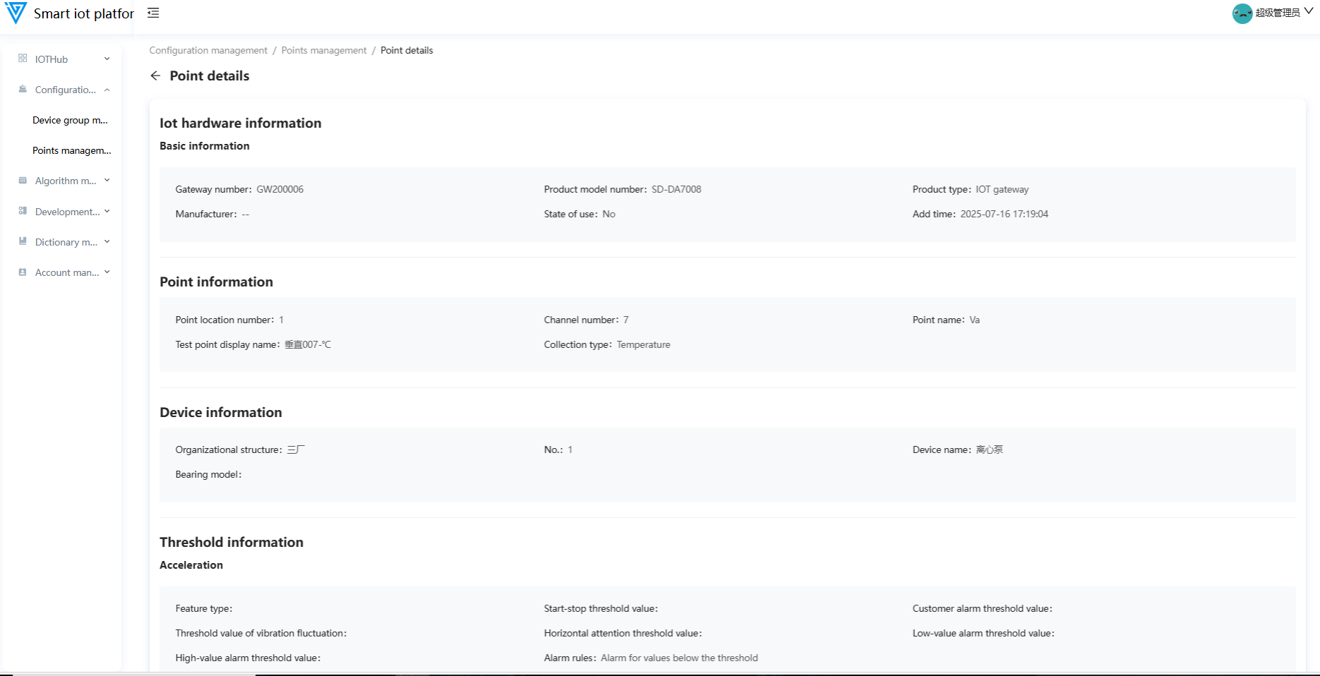
2.2 Viewing Details
Click the Details button behind a monitoring point to view its specific details.
Algorithm Management
1. Algorithm Management
1.1 Function Overview
Administrators can query algorithms by name/unit type, add/download/set as default, and record version/uploader metadata for traceability.

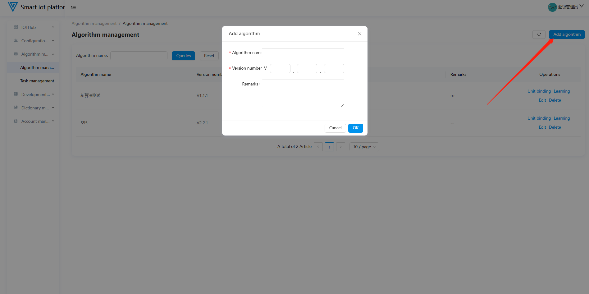
1.2 Algorithm Addition
Click the "Add Algorithm" button in the upper right corner of the page to open the algorithm addition popup. Fill in the required information and click the "Confirm" button to successfully add the algorithm.
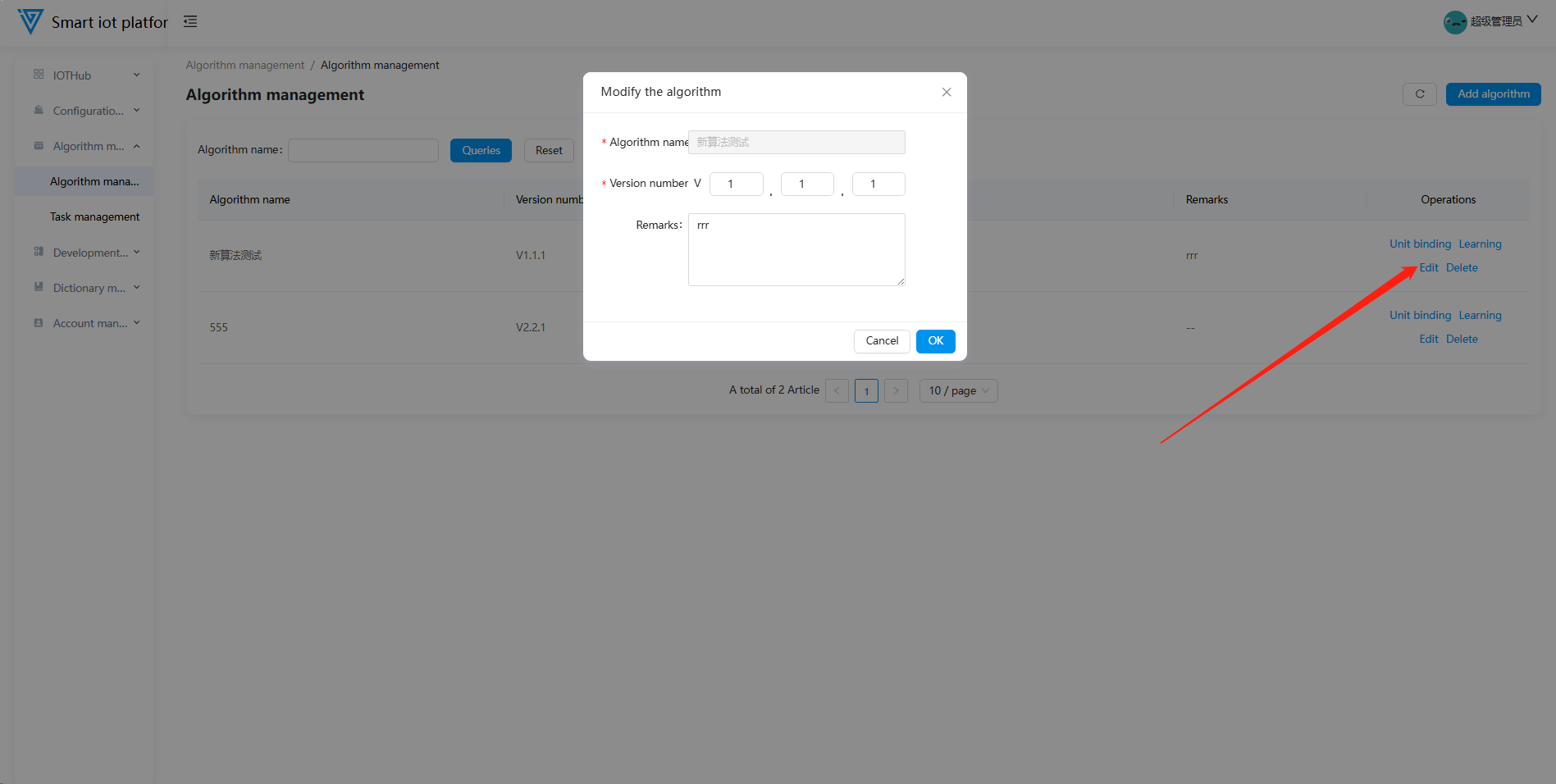
1.3 Algorithm Editing
To edit an existing algorithm, click the "Edit" button to open the algorithm modification popup. After making the necessary changes, click the "Confirm" button to update the algorithm successfully.
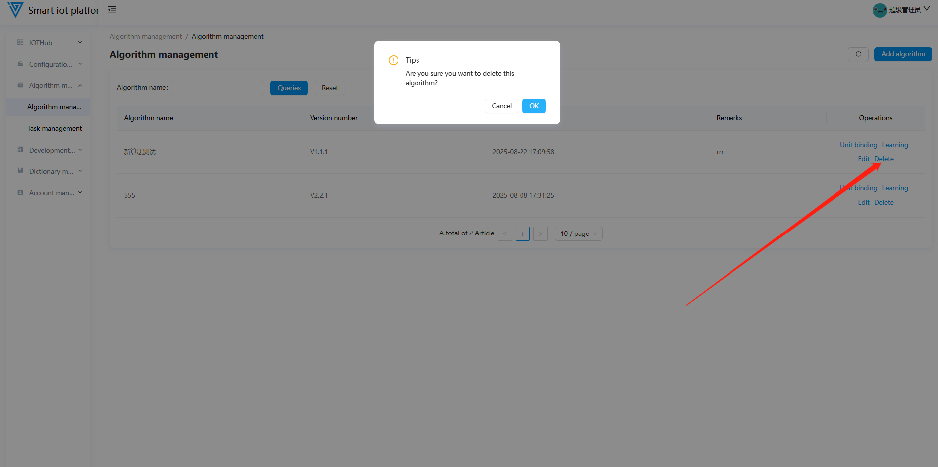
1.4 Algorithm Deletion
Algorithms that are not bound to any algorithm stream can be deleted. For algorithms already bound to an algorithm stream, unbinding must be performed before deletion.
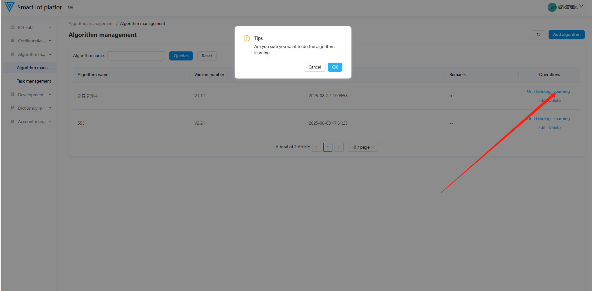
1.5 Algorithm Learning
Once an algorithm is used by an algorithm stream, automatic learning tasks will be created when the bound equipment data meets the auto-learning conditions. Users can also manually trigger a learning task by clicking the "Learn" button on the automatic learning algorithm management page.
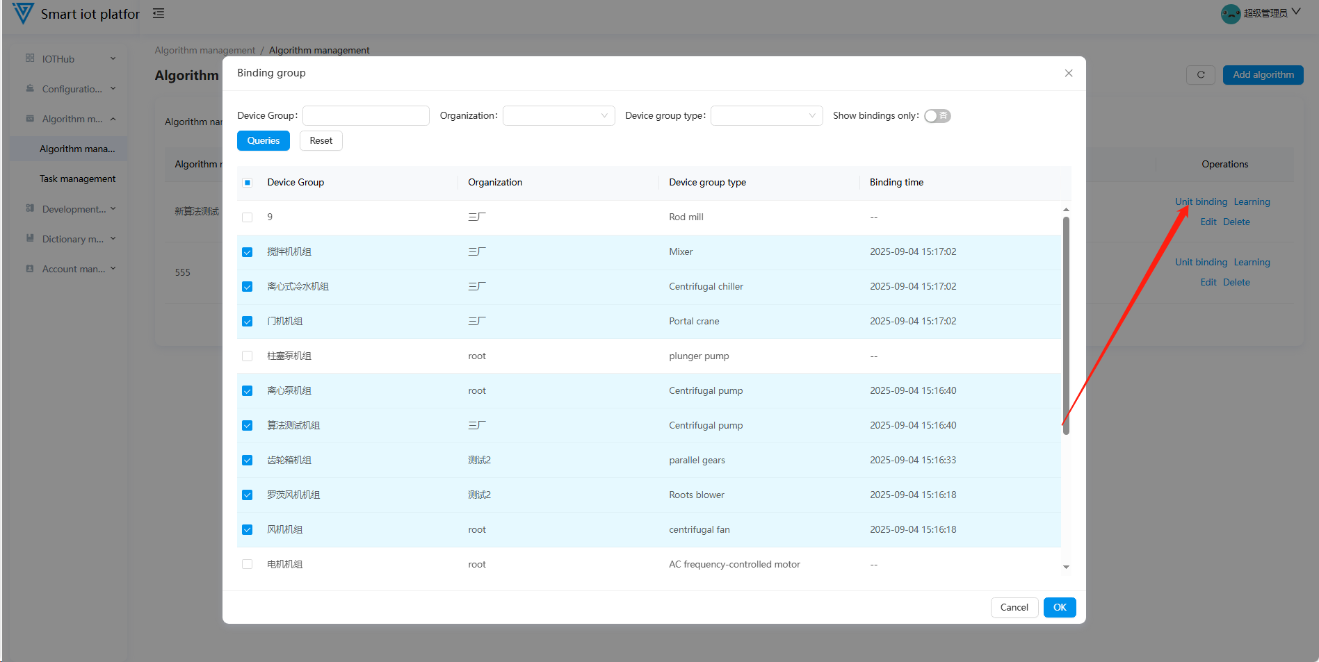
1.6 Equipment Binding
Click the "Equipment Binding" button in the list to enter the algorithm-equipment binding popup. Select the equipment units to be bound to the algorithm stream and click the "Confirm" button to complete the binding operation.
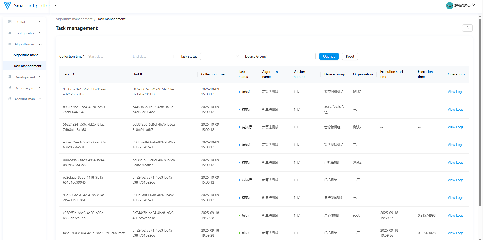
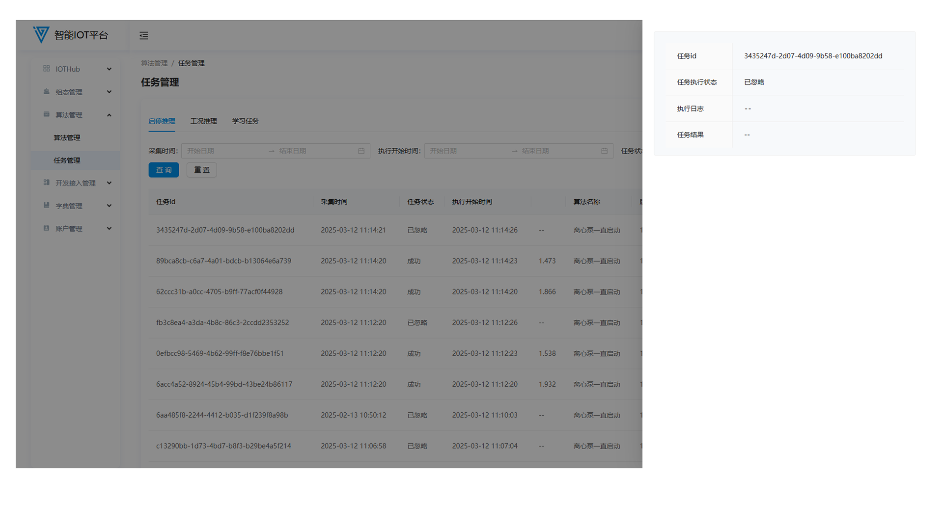
2.Task Management
2.1 Functional Overview
The Task Management module primarily displays information about AI inference and learning tasks. Queries can be performed based on task status, acquisition time, and equipment unit name.
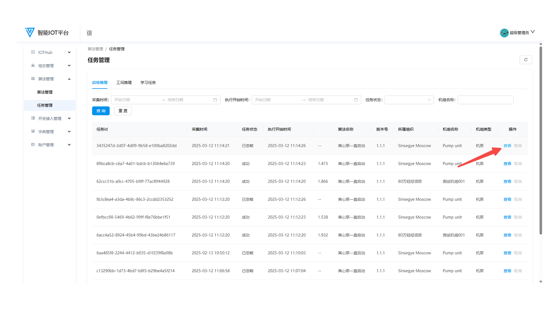
2.2 Task details
Click View button at the back of the task to pop up the details window of the task clicked, which displays the basic information, data information and log information of the task.
Development Access Management
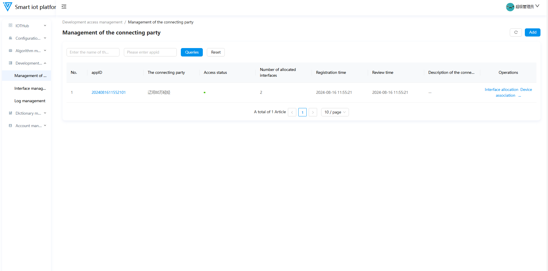
1. Management of liaison party
1.1 Functional Overview
The Integration Partner Management module primarily supports operations such as adding partners, editing partner information, interface allocation, device association, enabling/disabling partners, and deleting partners.
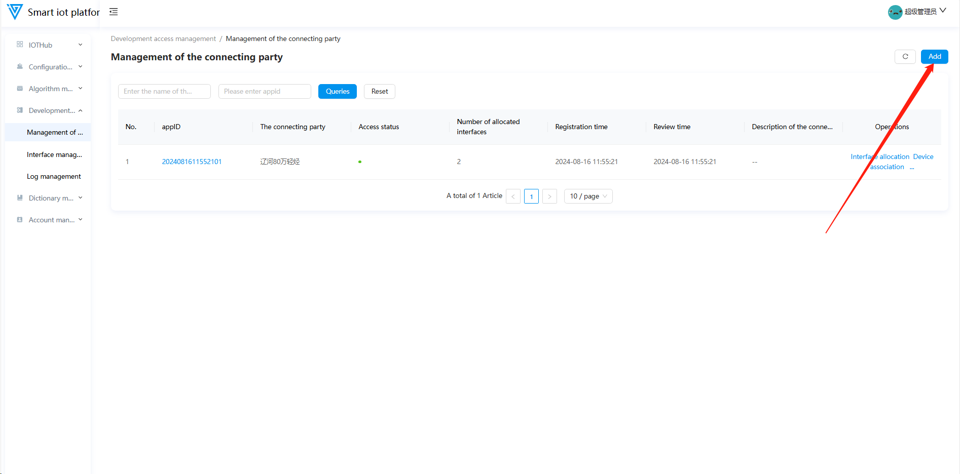
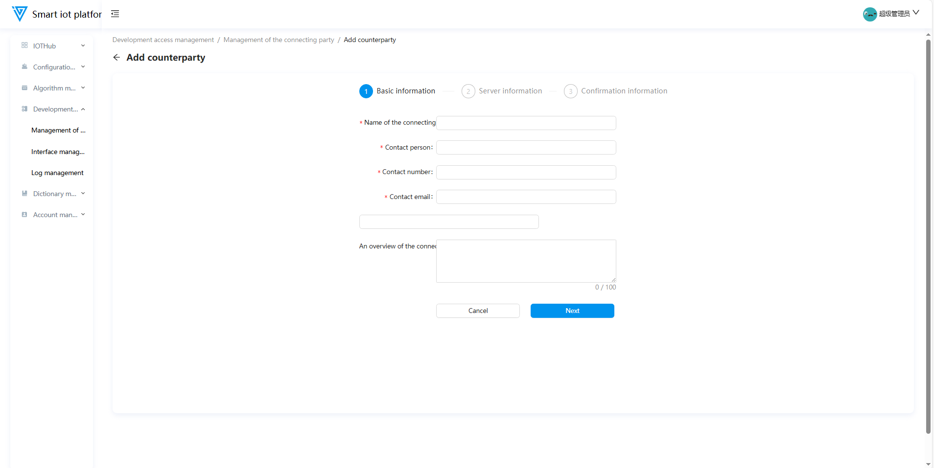
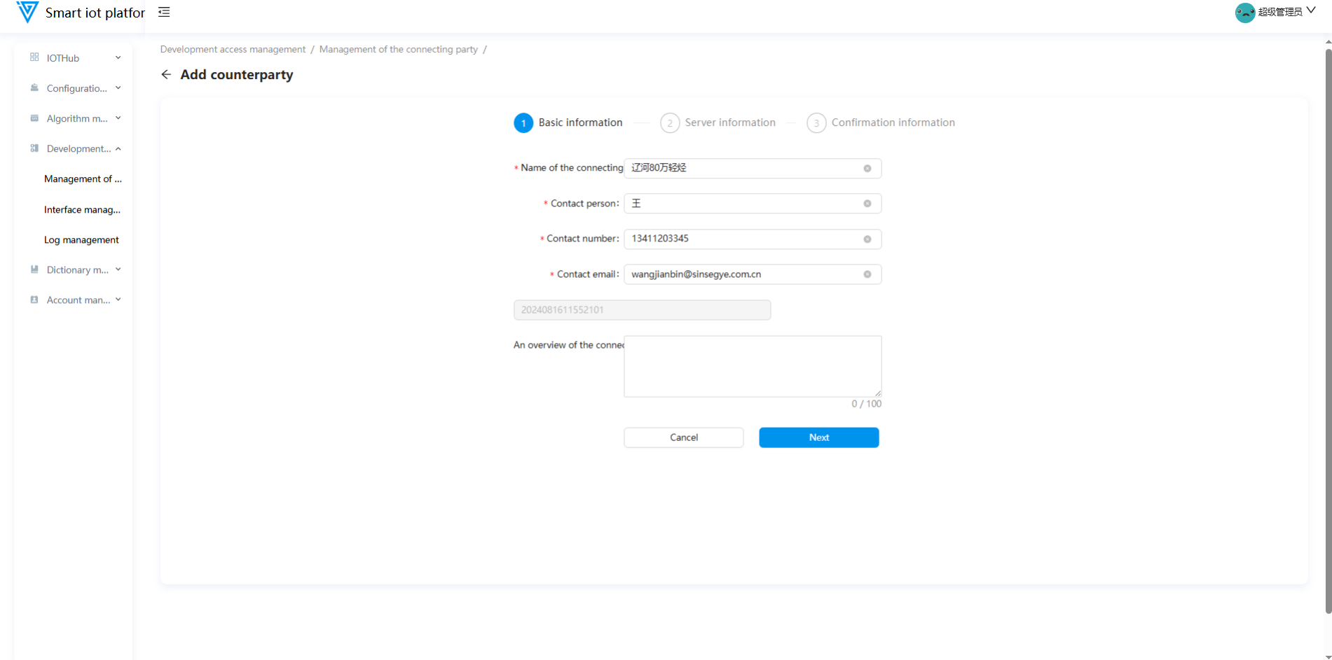
1.2 Adding an Integration Partner
Navigate to the Integration Partner Management page, click the "Add" button in the upper right corner, and enter the partner addition interface. Fill in the basic information and server details of the partner, then click the "Submit" button to complete the addition.
1.3 Editing an Integration Partner
Existing integration partners can be edited. Hover the mouse over the "..." menu, click the "Edit" button to enter the editing interface, and modify the partner details as needed.
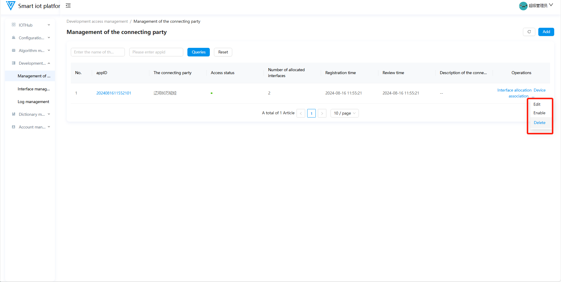
1.4 Enabling/Disabling an Integration Partner
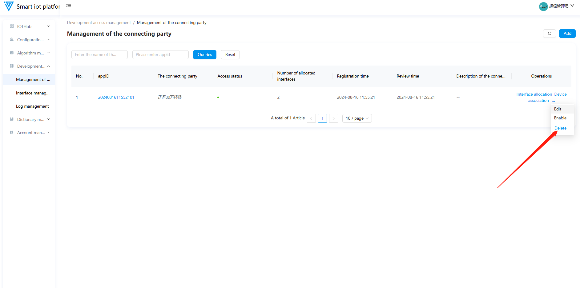
Newly added integration partners are enabled by default. Click the "Disable" button to change the partner’s status to disabled. Disabled partners can be re-enabled.
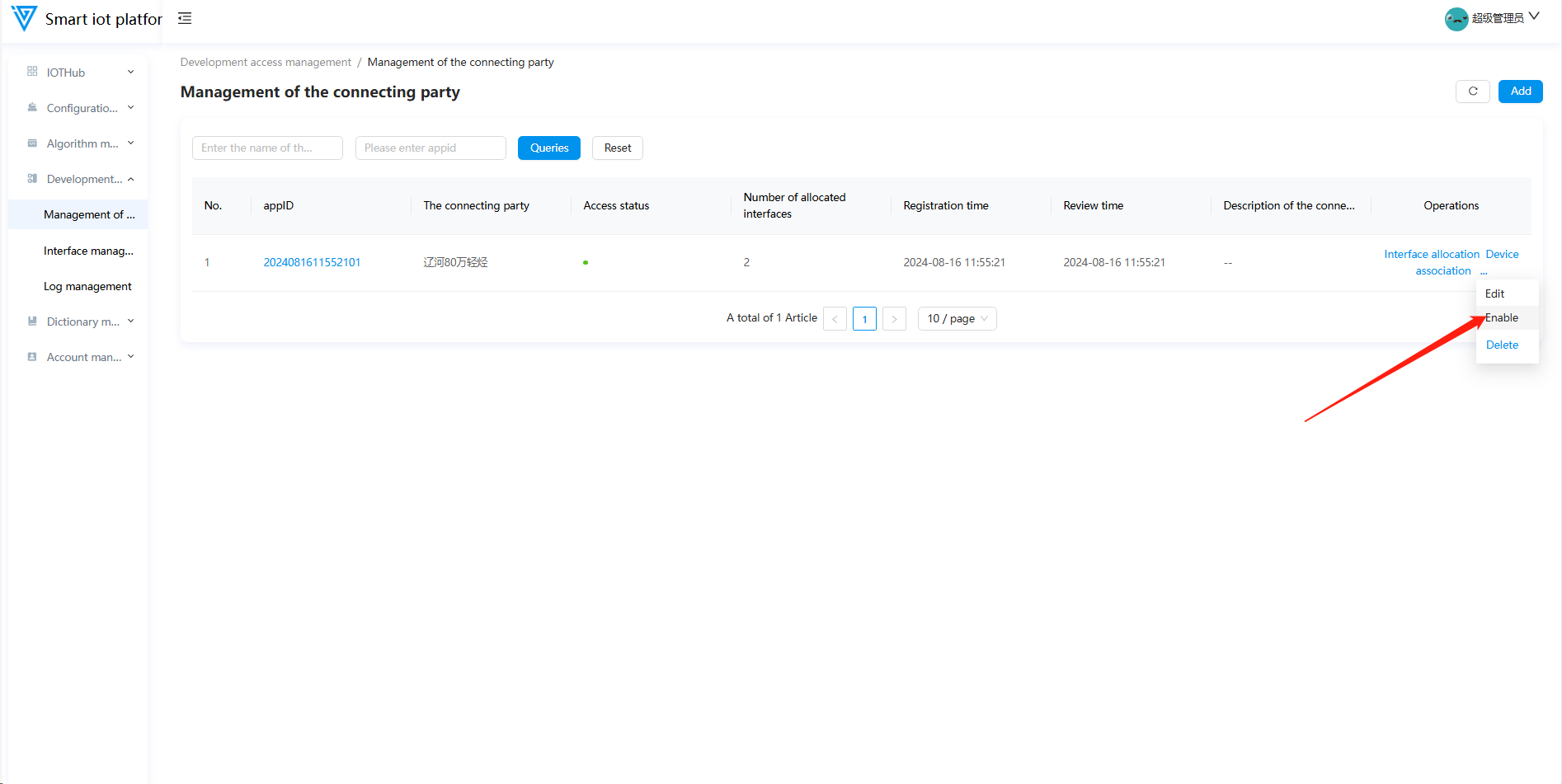
Only disabled partners can be deleted.
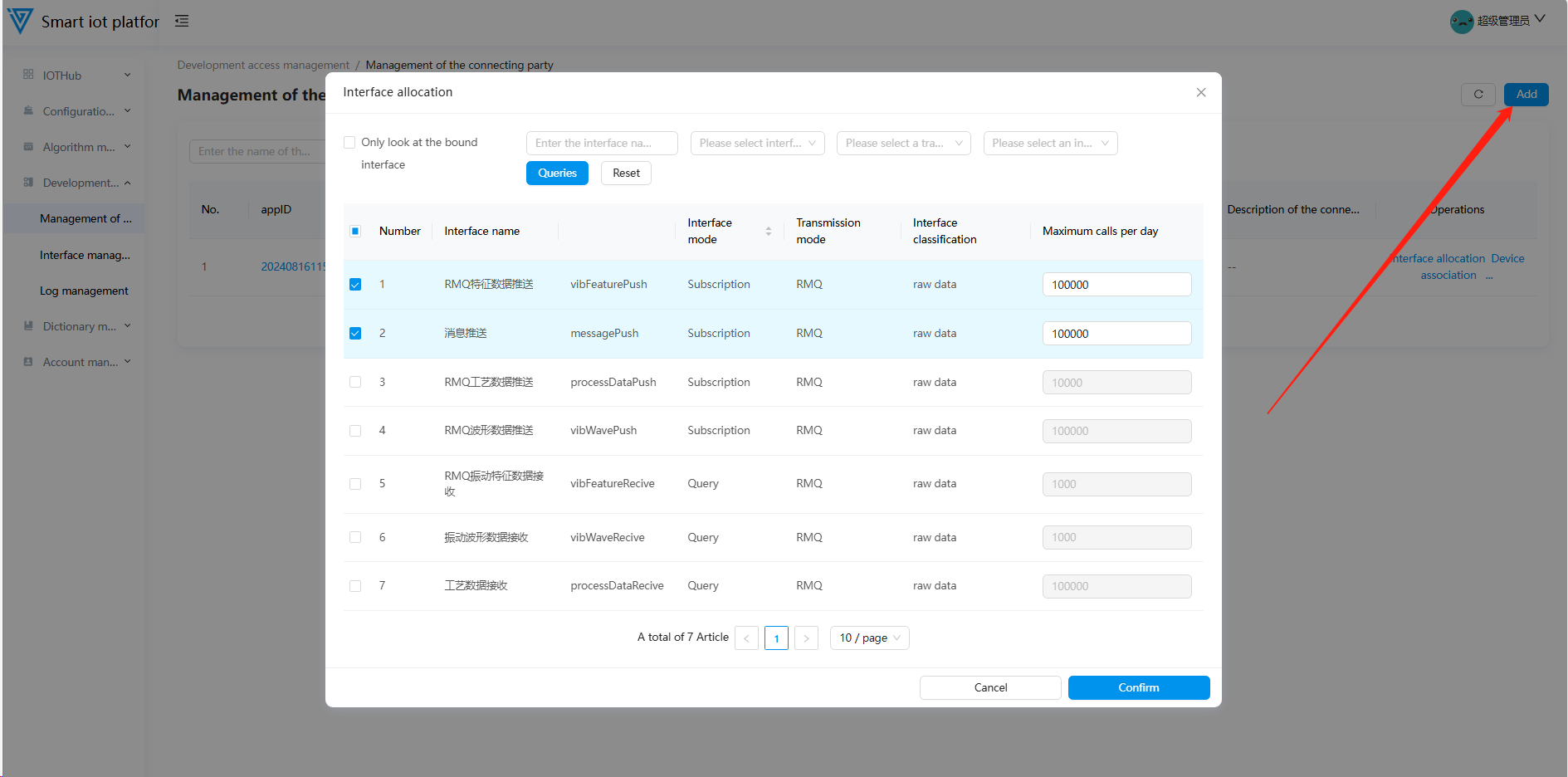
1.5 Interface Allocation
Data transmission and reception for integration partners are handled through interfaces. During partner management, interface allocation is performed by clicking the "Interface Allocation" button on the interface, which opens a pop-up window. In this window, assign the corresponding interfaces and set the maximum daily call count.
Once the daily call limit is exceeded, data reception and data pushing will be suspended for the remainder of the day.
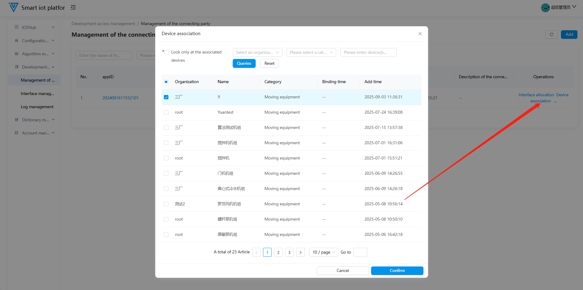
1.6 Device Association
After associating devices with an integration partner, data generated by the devices can be pushed to users via the partner. Alternatively, device information received from users can be displayed on the intelligent diagnosis platform. To associate devices, click the "Device Association" button on the page, check the devices to be associated in the popup window, and click "Confirm."
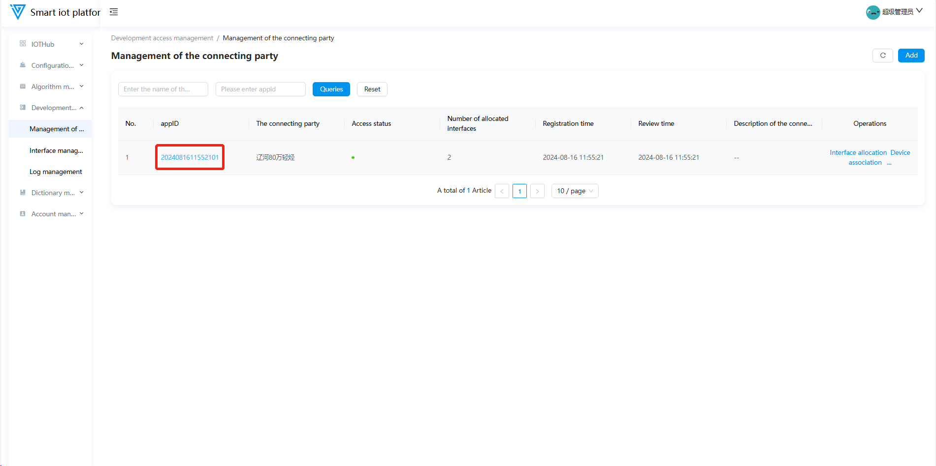
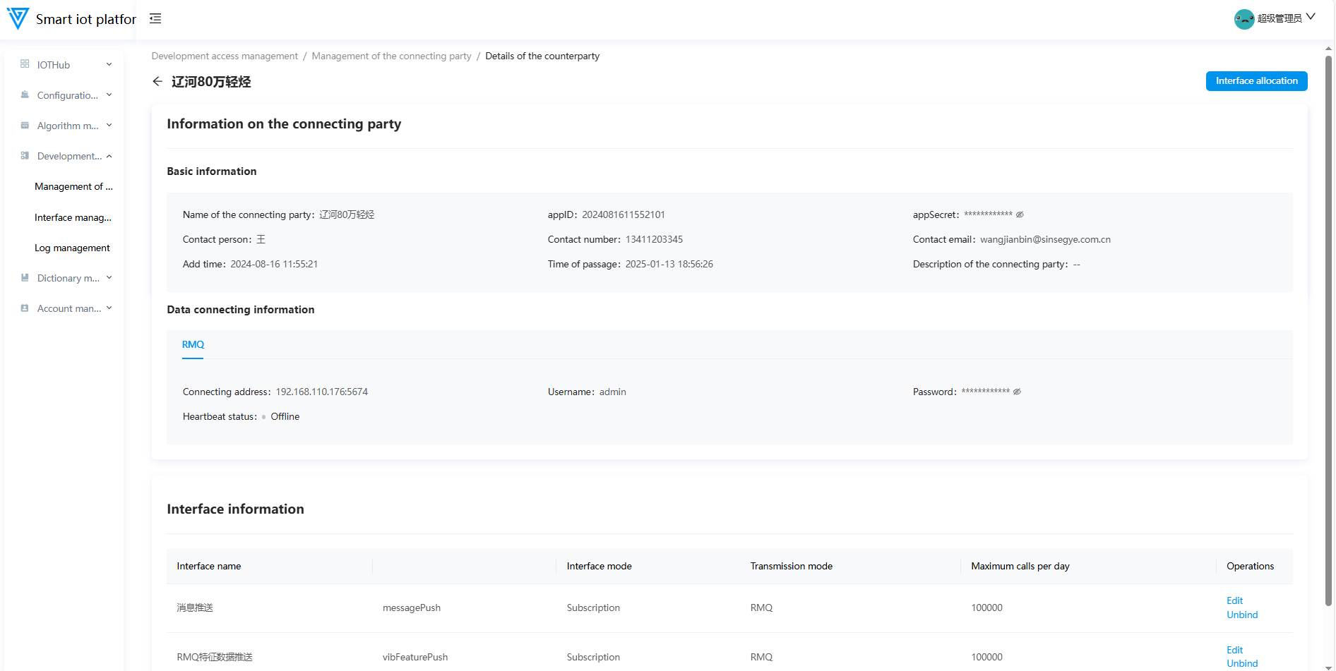
1.7 Integration Partner Details
Each added integration partner is assigned an appID. Clicking on the partner’s appID will navigate to the partner details page, displaying basic information, data integration details, and interface binding information.
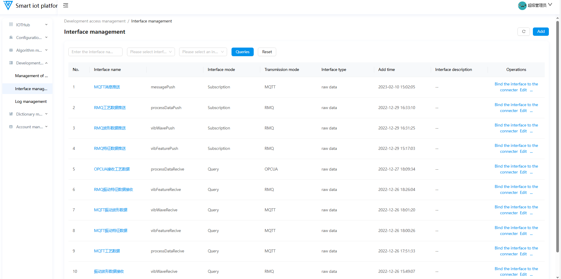
2.Interface Management
2.1 Functional Overview
The Interface Management module primarily supports operations such as adding interfaces, editing interfaces, binding integration partners, enabling/disabling interfaces, and deleting interfaces.
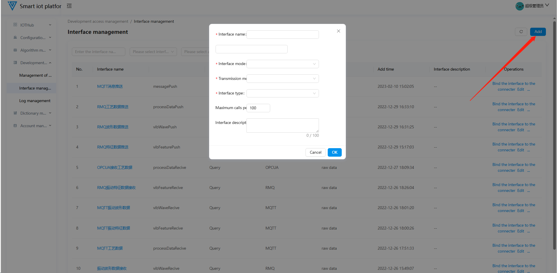
2.2 Adding an Interface
Click the "Add" button in the upper right corner of the page to open the interface addition pop-up window. After filling in the corresponding interface information, click the "Confirm" button to successfully add the interface.
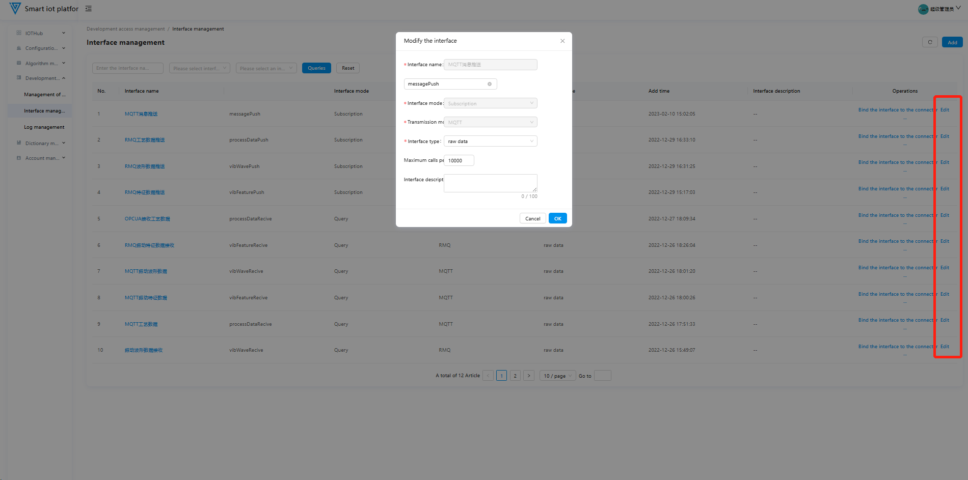
2.3 Editing an Interface
To update or modify an existing interface, click the "Edit" button on the page to open the editing pop-up window. After making the necessary changes, click the "Confirm" button to complete the interface editing operation.
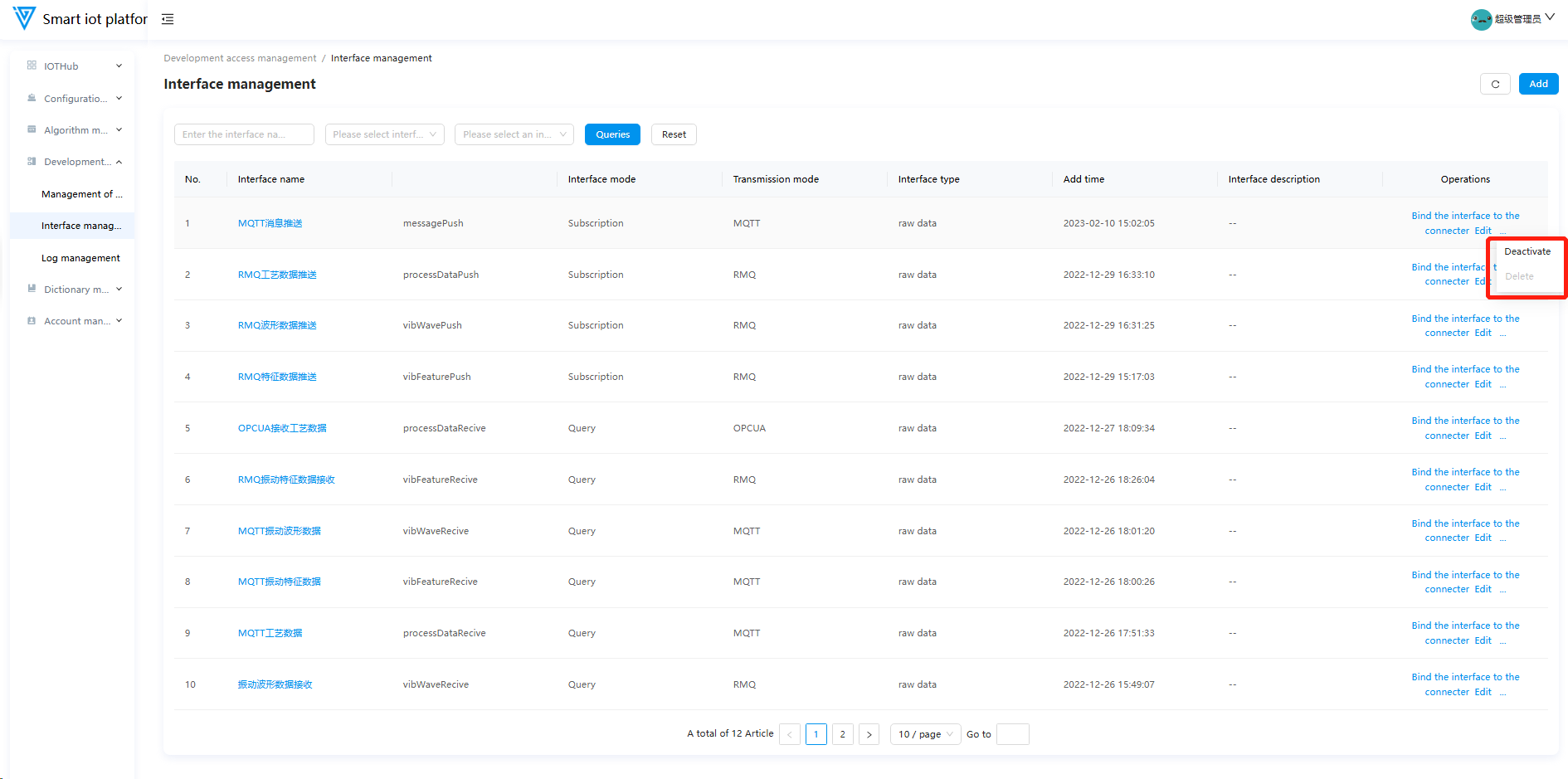
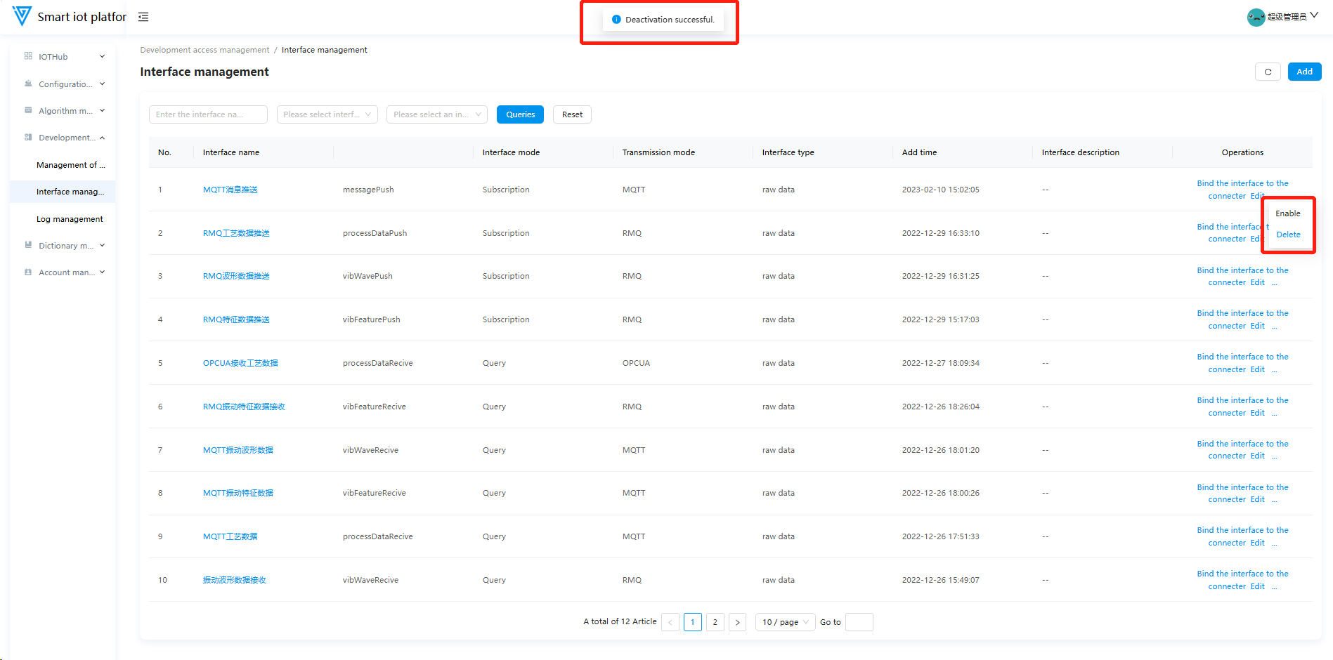
2.4 Enabling/Disabling and Deleting an Interface
Newly added interfaces are enabled by default. Click the "Disable" button to toggle the status. Only interfaces in the disabled state can be deleted.
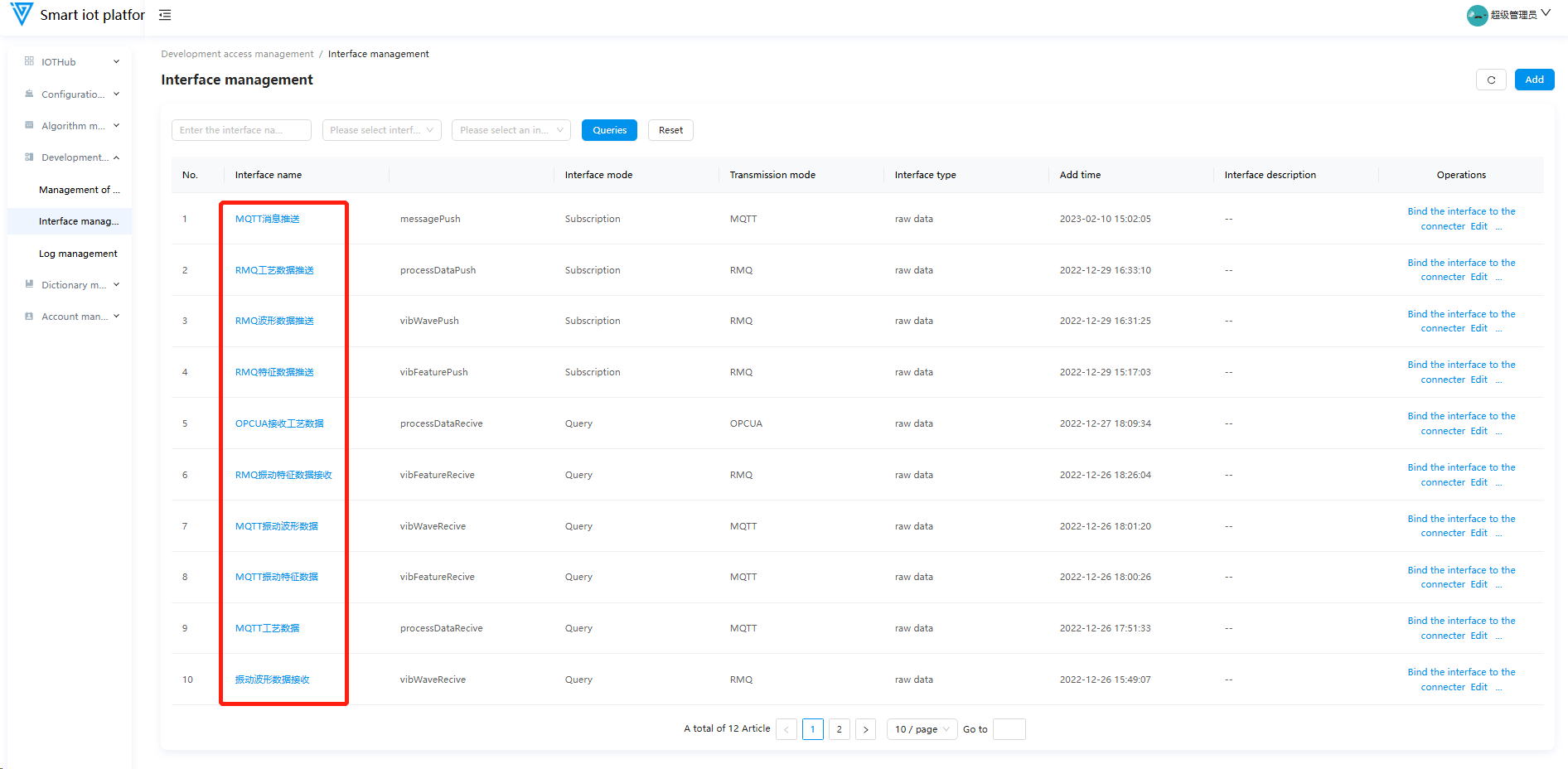
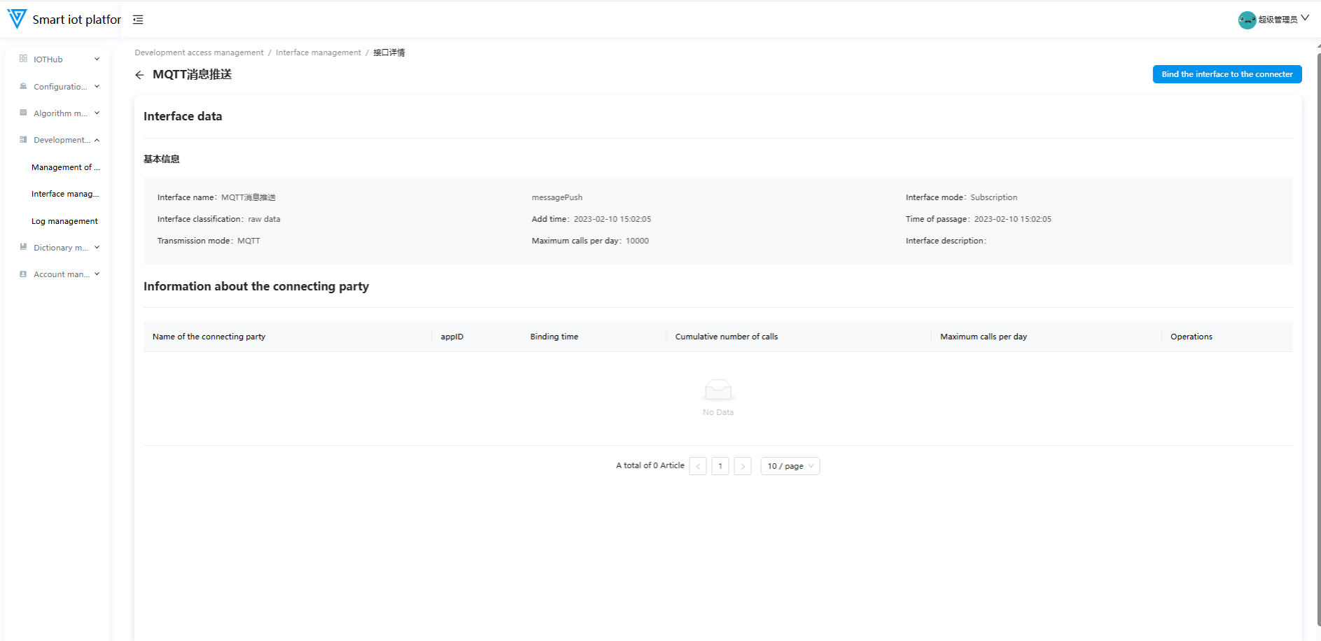
2.5 Interface Details
Click on the interface name to navigate to the interface details page, which displays the interface information and integration partner information.
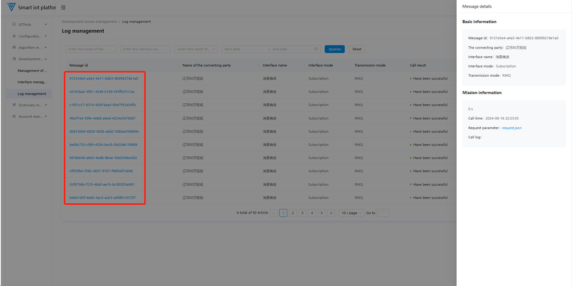
3. Log Management
3.1 Functional Overview
The Log Management module primarily displays message reception and data push logs of integration partners. Log queries can be performed based on integration partner name, interface name, call result, and call time.
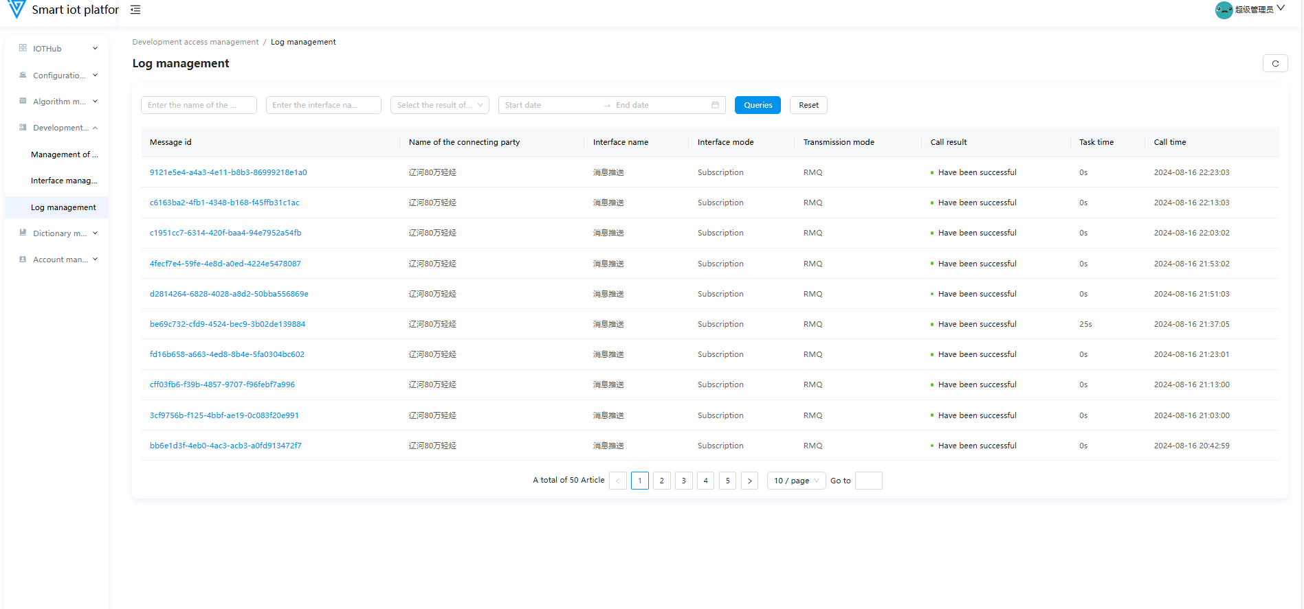
3.2 Viewing Details
Click on the message ID of a log entry to view the detailed information of the message.
Dictionary Management
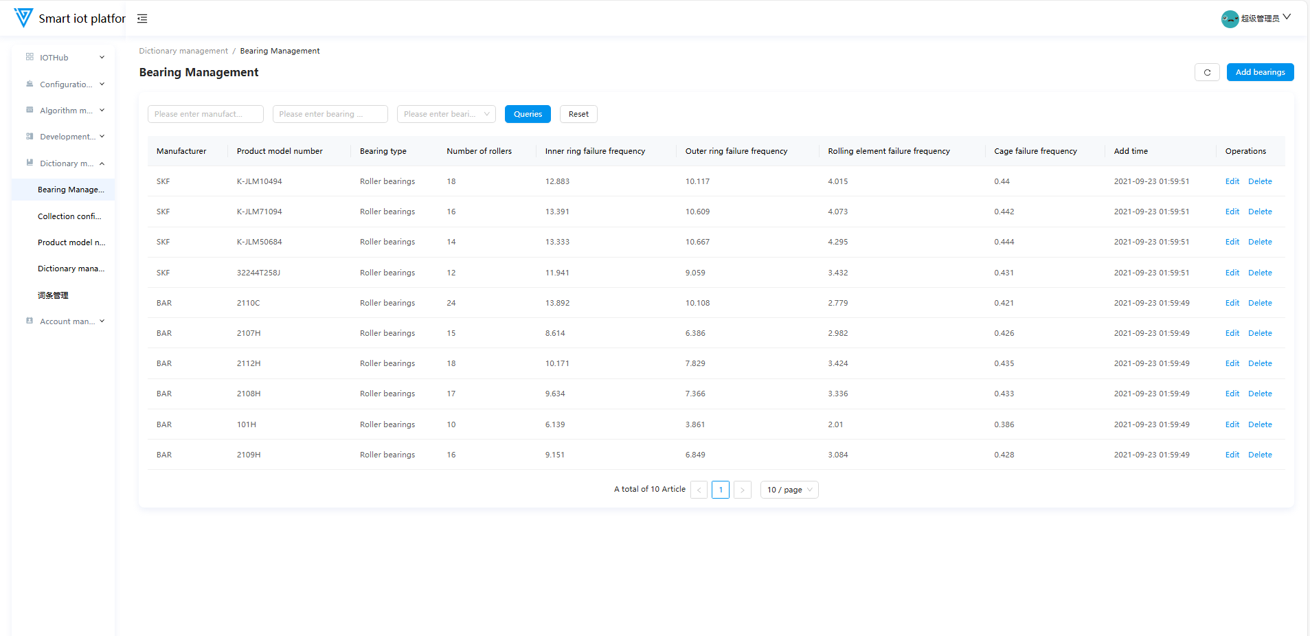
1. Bearing Management
1.1 Functional Overview
The Bearing Management module primarily supports operations such as adding, editing, and deleting bearings.
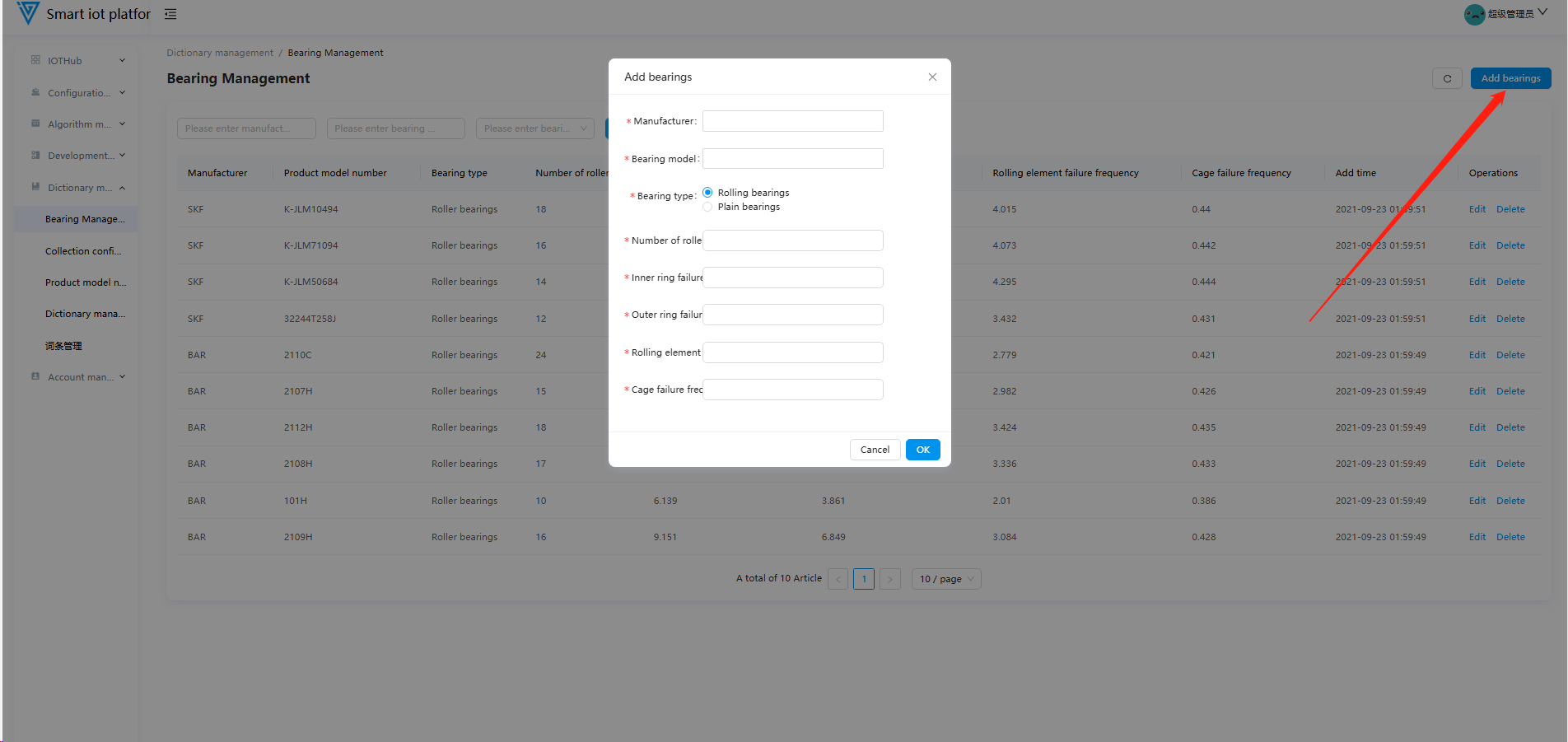
1.2 Adding a Bearing
Click the "Add Bearing" button in the upper right corner of the page to open the bearing addition pop-up window. After filling in the relevant bearing information, click the "Confirm" button to successfully add the bearing.
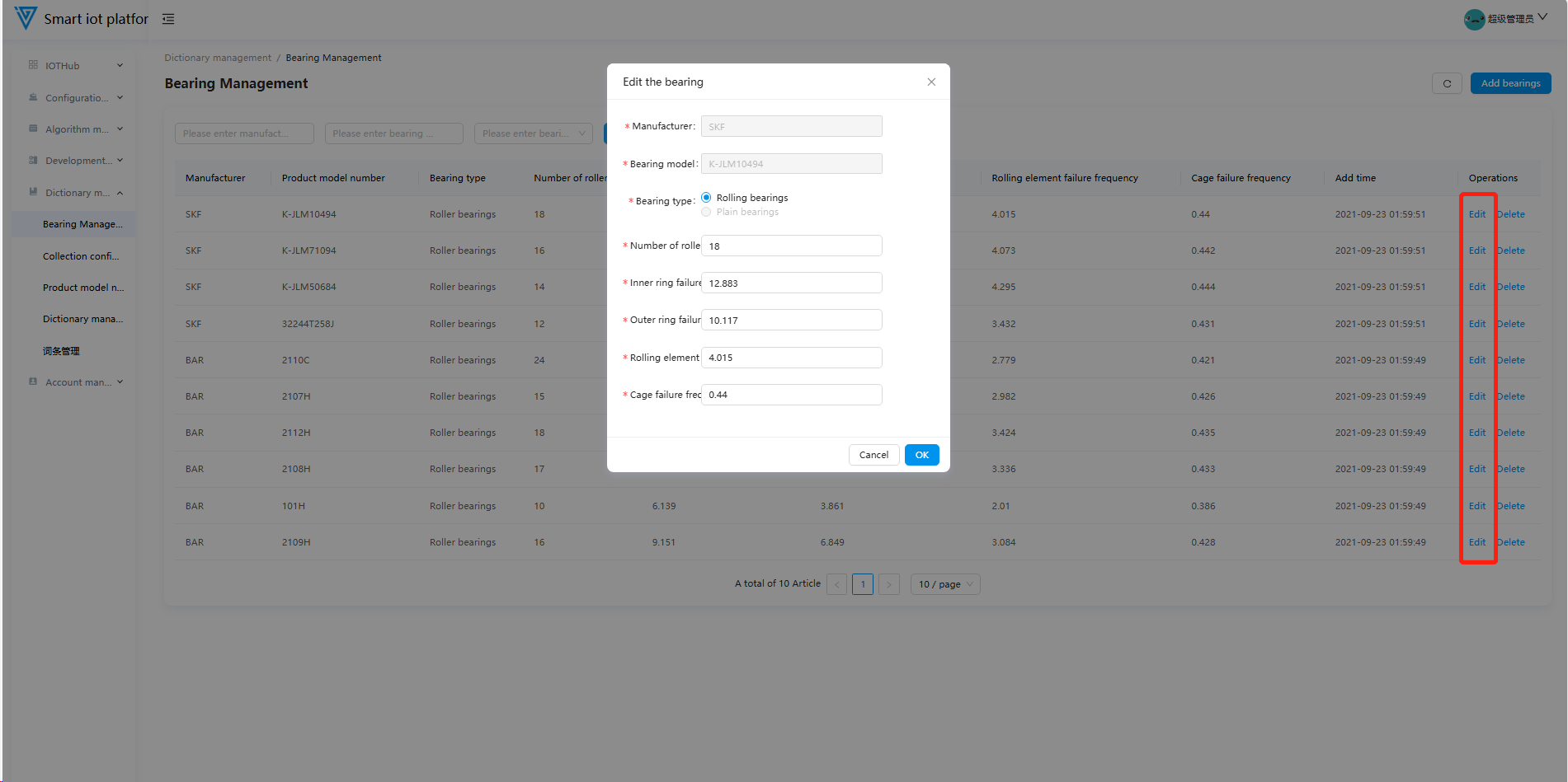
1.3 Editing a Bearing
Added bearings are displayed in the bearing list page of the Bearing Management module. Click the "Edit" button for a bearing to enter the editing pop-up window for the selected bearing. After updating the bearing information, click the "Confirm" button to complete the editing operation.
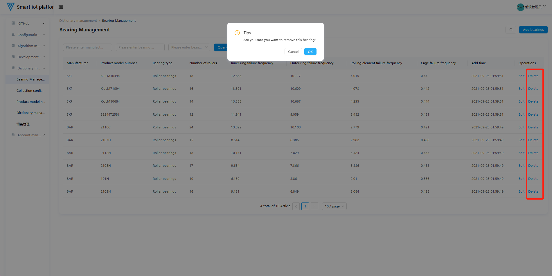
1.4 Deleting a Bearing
Click the "Delete" button on the bearing list page. After the confirmation pop-up appears, click the "Confirm" button to delete the bearing. Note: Bearings that are already in use cannot be deleted.
2. Acquisition Configuration
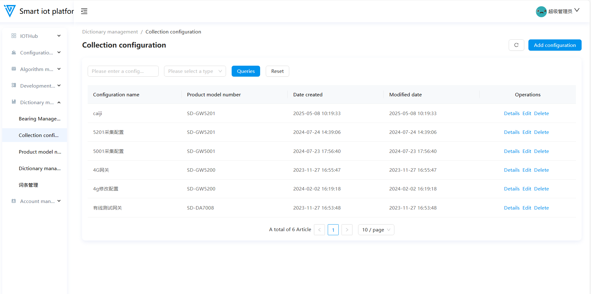
2.1 Functional Overview
The Acquisition Configuration module primarily supports operations such as adding, editing, and deleting acquisition configurations.
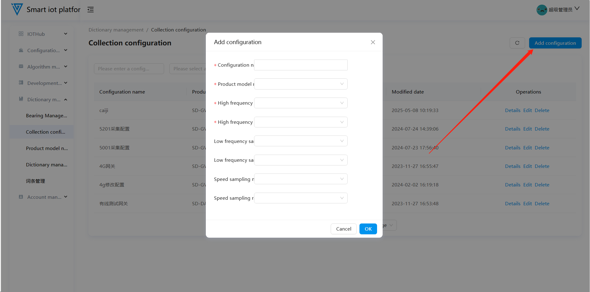
2.2 Adding an Acquisition Configuration
Click the "Add Configuration" button in the upper right corner of the page to enter the acquisition configuration addition pop-up window. After filling in the relevant information, click the "Confirm" button to complete the configuration addition.
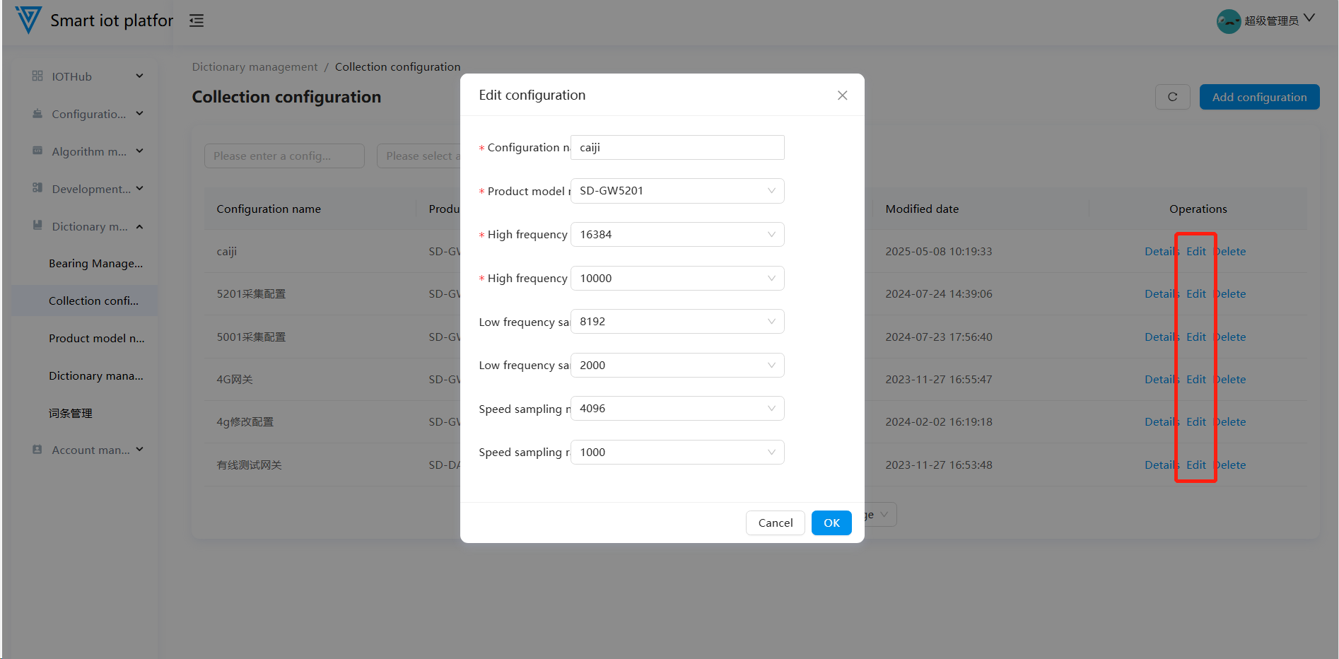
2.3 Editing an Acquisition Configuration
To update an existing acquisition configuration, click the "Edit" button on the page to enter the editing pop-up window. After making modifications, click the "Confirm" button to complete the editing operation.
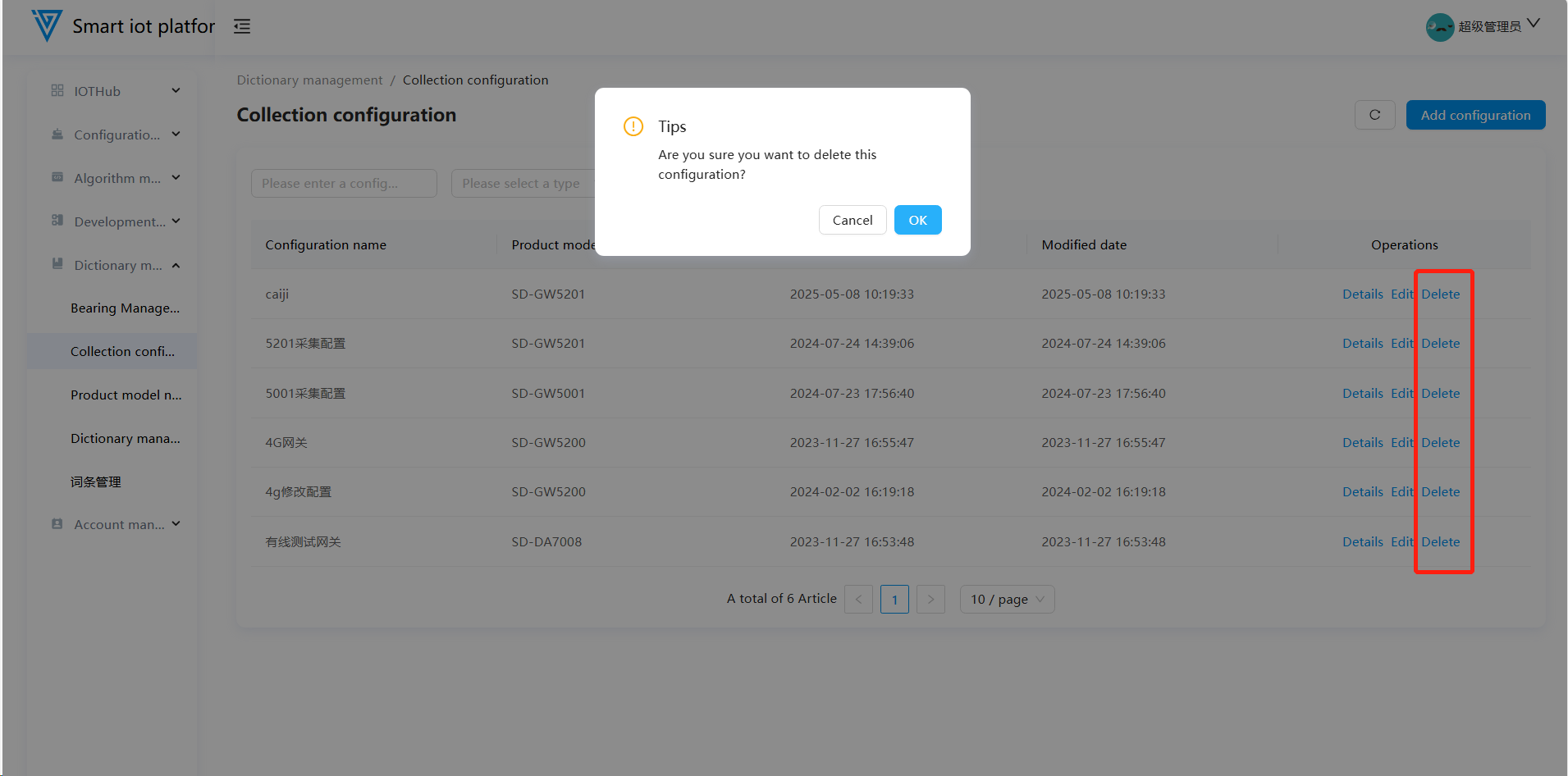
2.4 Deleting an Acquisition Configuration
Acquisition configurations that are already in use cannot be deleted. Click the "Delete" button on the page, and after the confirmation pop-up appears, click "Confirm" to delete an unused acquisition configuration.
3. Product Models
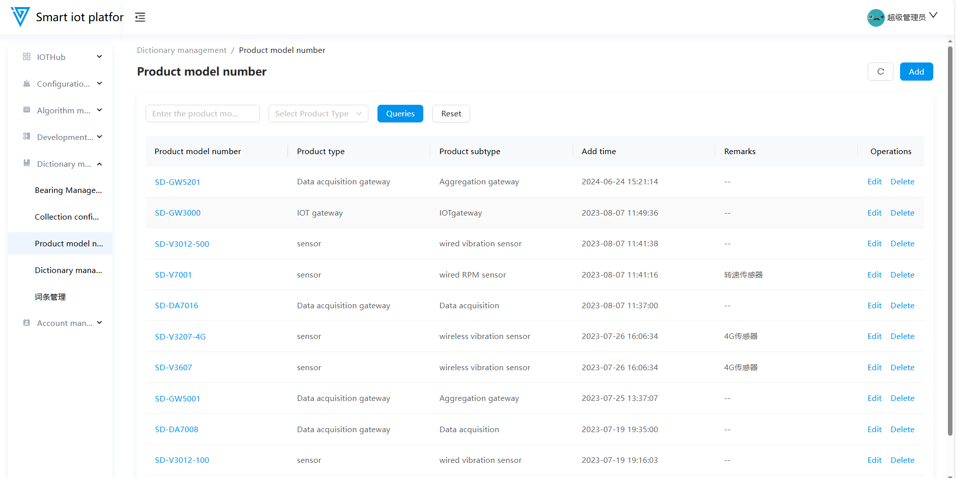
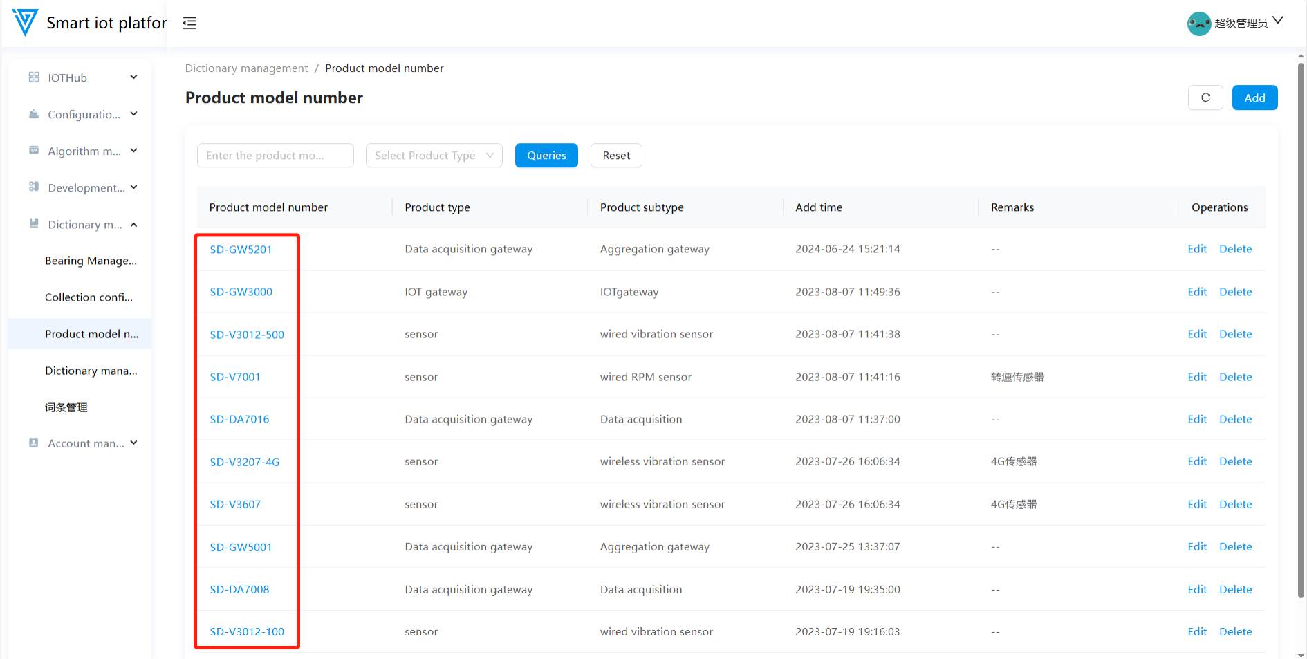
**3.1 Functional Overview **
The Product Models module allows users to add, edit, and delete product models. Product models are primarily used for sensor addition, data acquisition gateway addition, and acquisition configuration addition.
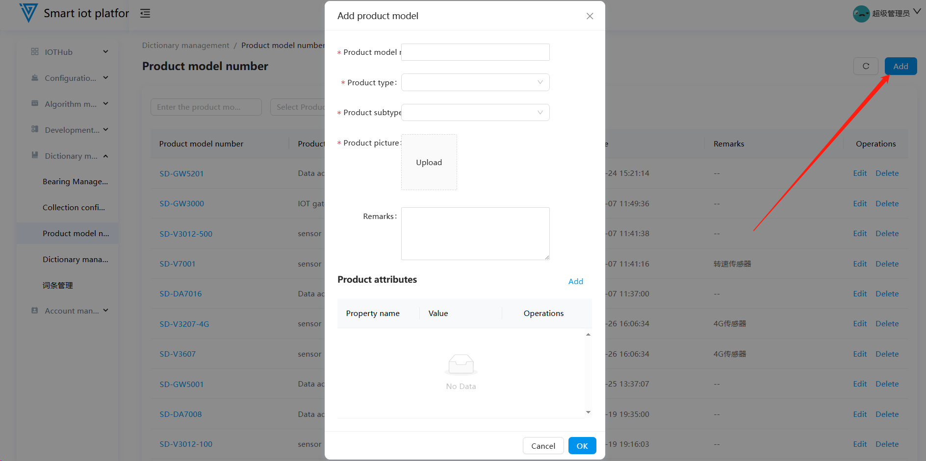
3.2 Adding a Product Model
Navigate to the Product Models list page, click the "Add" button in the upper right corner to open the product model addition pop-up window. Fill in the product model, product type, product subtype, and product image. In the product attributes section, enter the number of channels, transmission method, and communication method. Click the "Confirm" button to successfully add the product model. The remarks field allows users to add custom notes. To add other attribute information to the product model, users can independently select product attribute information added in the dictionary.
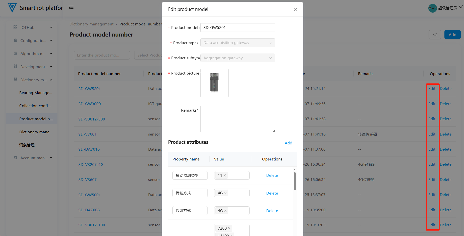
3.3 Editing a Product Model
Added product models are displayed on the product models list page in reverse chronological order of addition. Click the "Edit" button for the selected product model to enter the editing pop-up window. The product model, product type, and product subtype cannot be edited; other information can be updated.
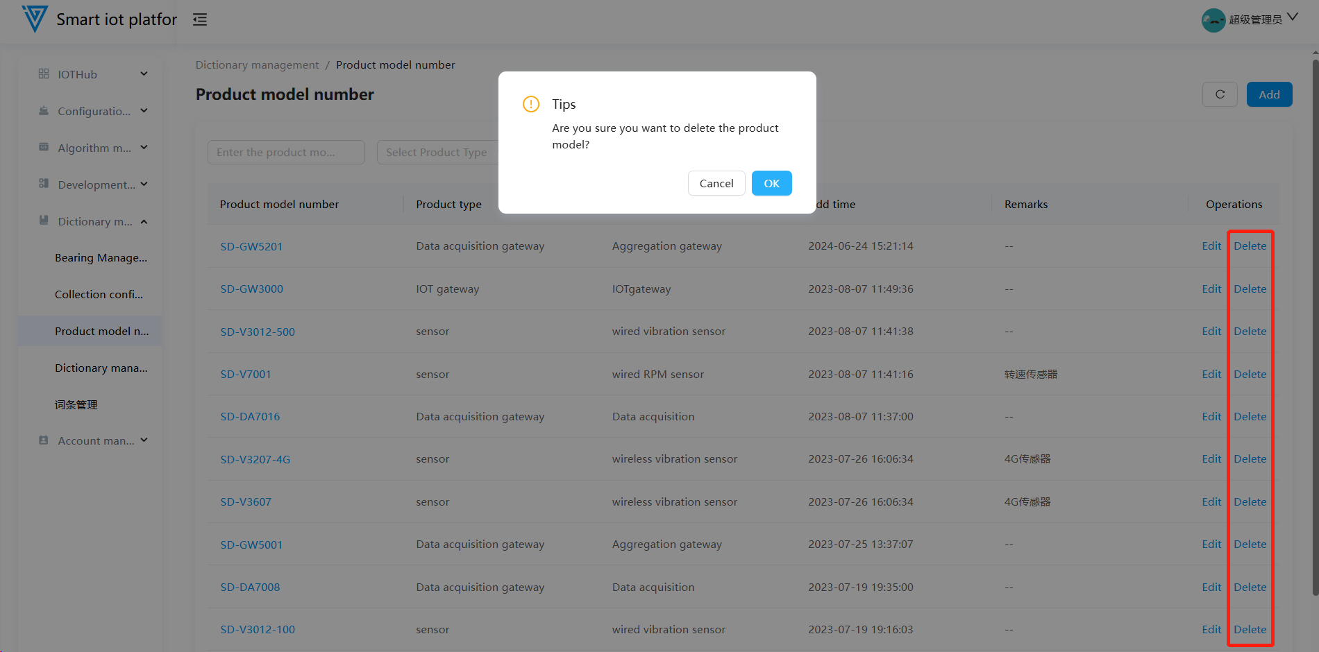
3.4 Deleting a Product Model
Product models that are already in use cannot be deleted. Only unused product models can be deleted.
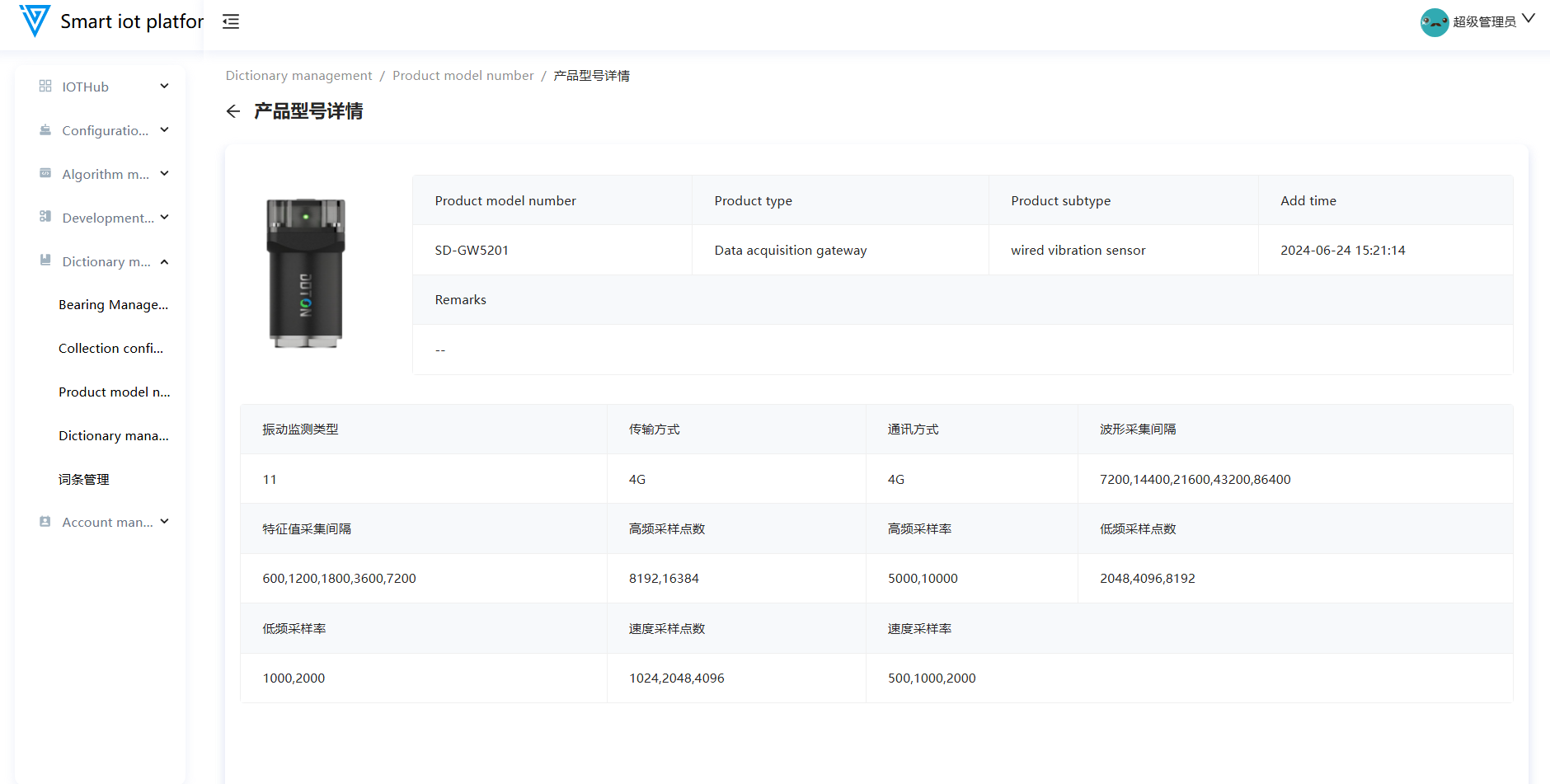
3.5 Product Model Details
Click on the product model name in the list page to navigate to the product model details page, which displays basic information, attribute information, and acquisition configuration information of the product model.
4. Dictionary Management
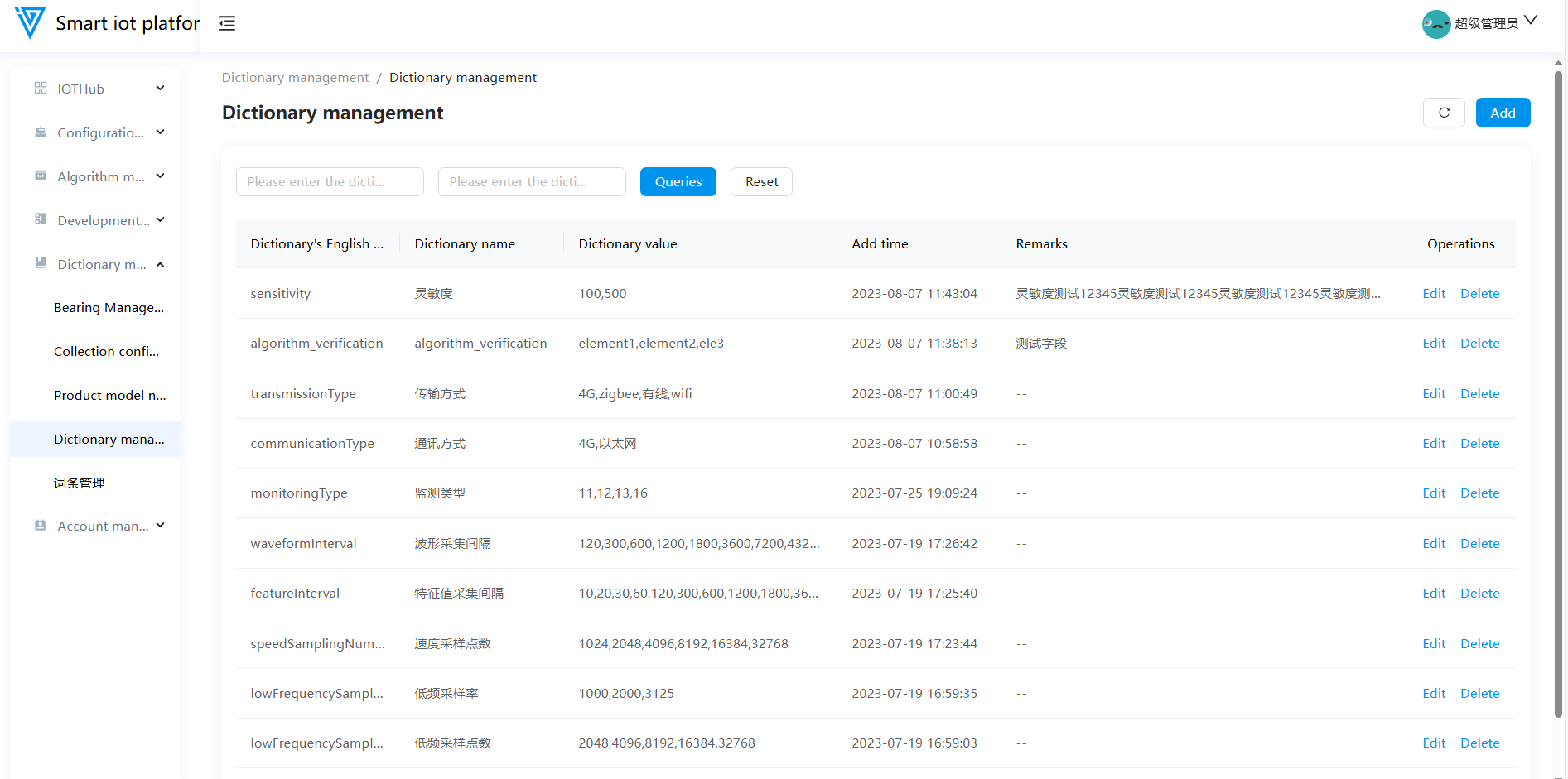
4.1 Functional Overview
The Dictionary Management module primarily allows users to independently edit and add product model attribute information and other attribute information. It mainly supports editing and deleting dictionary entries.
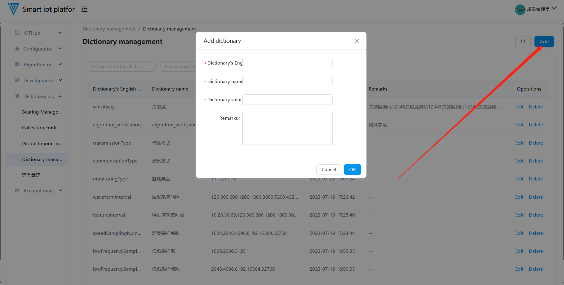
4.2 Adding Dictionary Entries
Dictionary addition refers to system-built dictionary information and cannot be performed on the page.
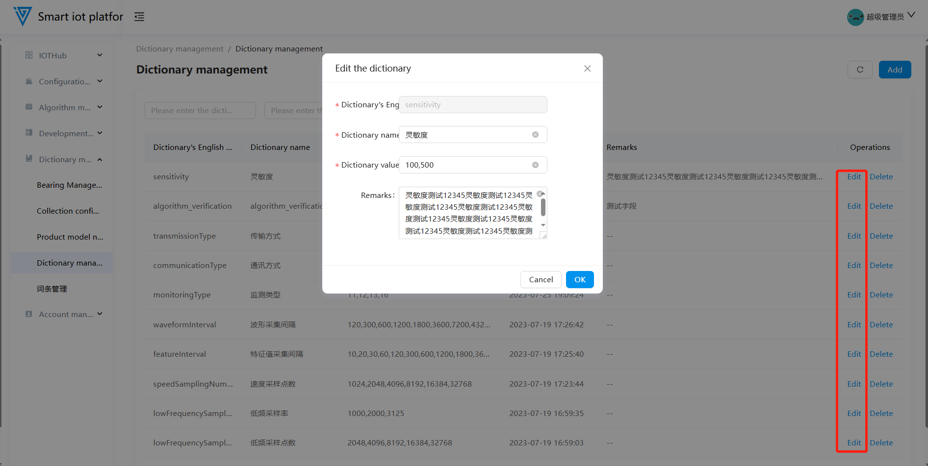
4.3 Editing Dictionary Entries
Added dictionary entries are displayed on the dictionary management list page in reverse chronological order of addition. Click the "Edit" button for the selected dictionary entry to enter the editing pop-up window. The English name of the dictionary entry cannot be edited; other information can be updated.
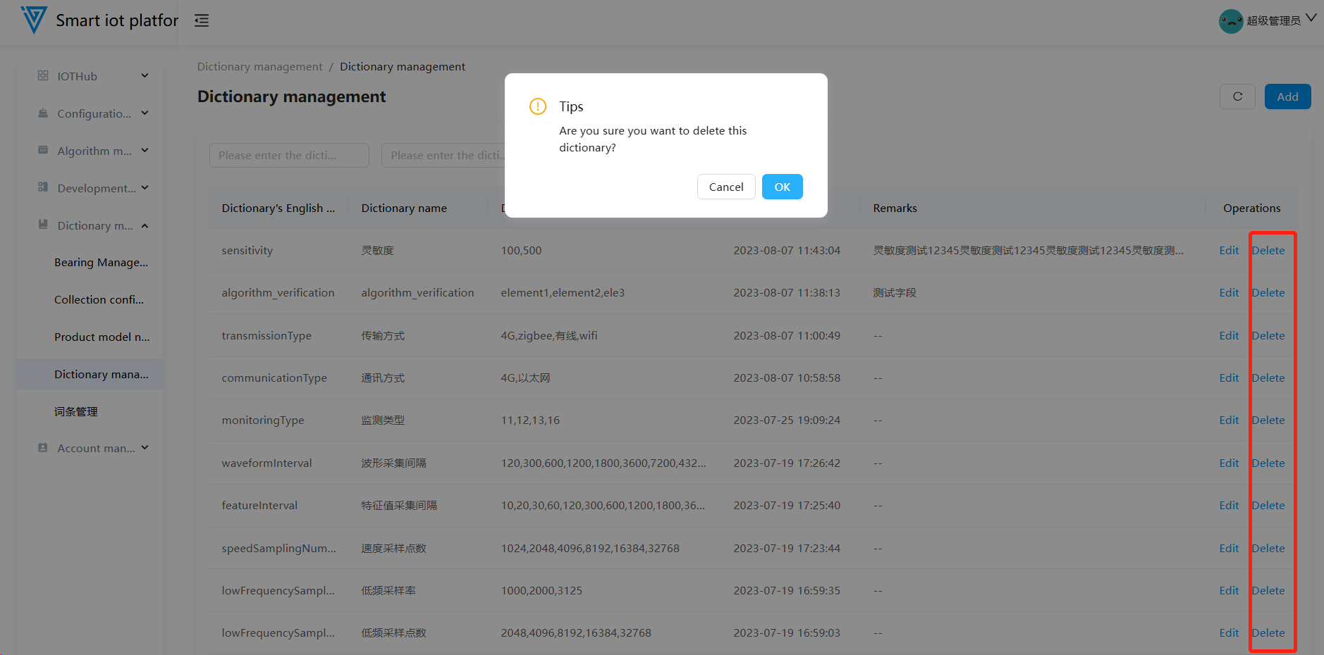
4.4 Deleting Dictionary Entries
Click the "Delete" button for the selected dictionary entry to delete it.
Account Management
1. User Management
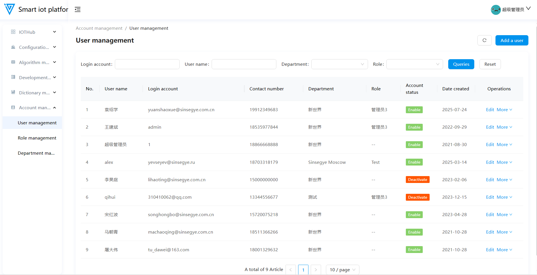
1.1 Functional Overview
The User Management module supports operations such as adding users, editing user information, resetting passwords, enabling/disabling accounts, and deleting users.
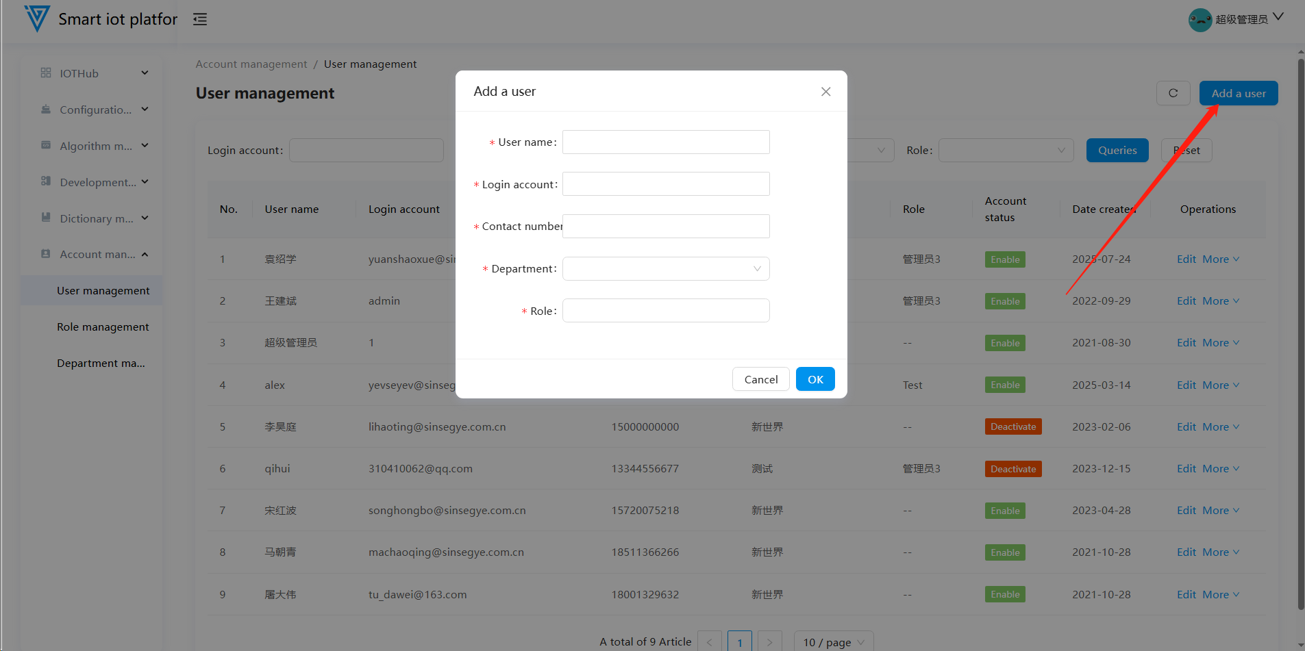
1.2 Adding a User
Click the "Add User" button in the upper right corner of the page to open the user addition pop-up window. Fill in the required information and click the "Confirm" button to complete the user addition process.
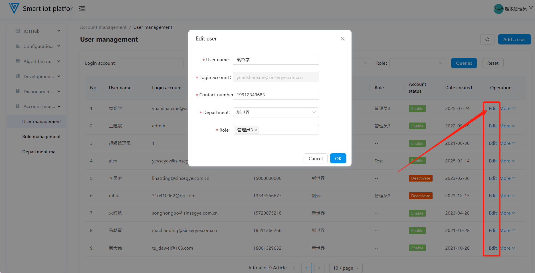
1.3 Editing a User
To update a user's name, contact number, department, or role, click the "Edit" button on the page to enter the editing pop-up window. After updating the relevant information, click the "Confirm" button to save the changes.
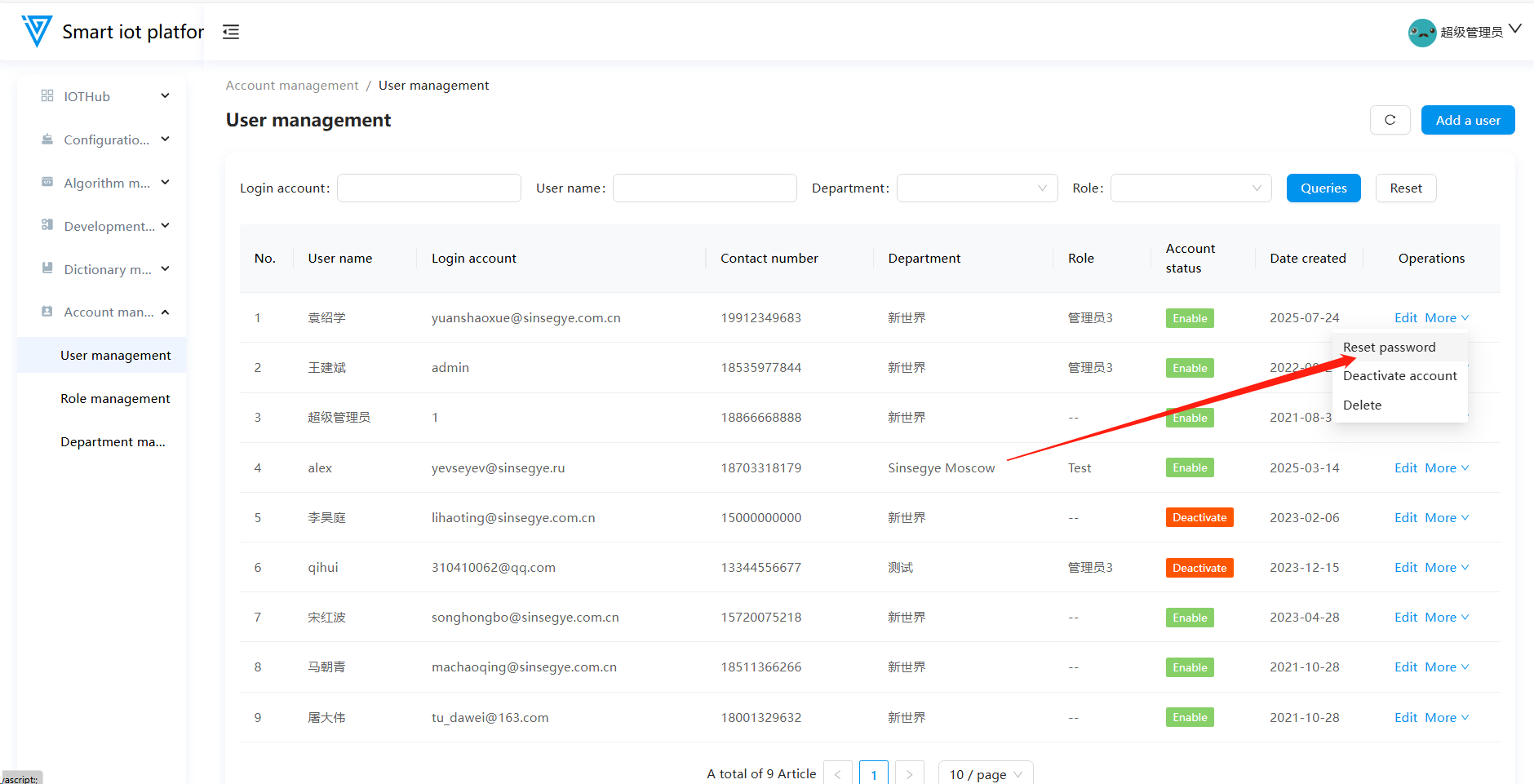
1.4 Resetting a Password
If a user forgets their password, the administrator can reset it. Hover over the "More" button on the page and click "Reset Password."
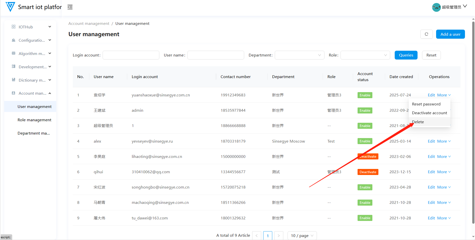
1.5 Disabling an Account
Accounts that are enabled can be disabled. Once disabled, the account will no longer have access to the platform.
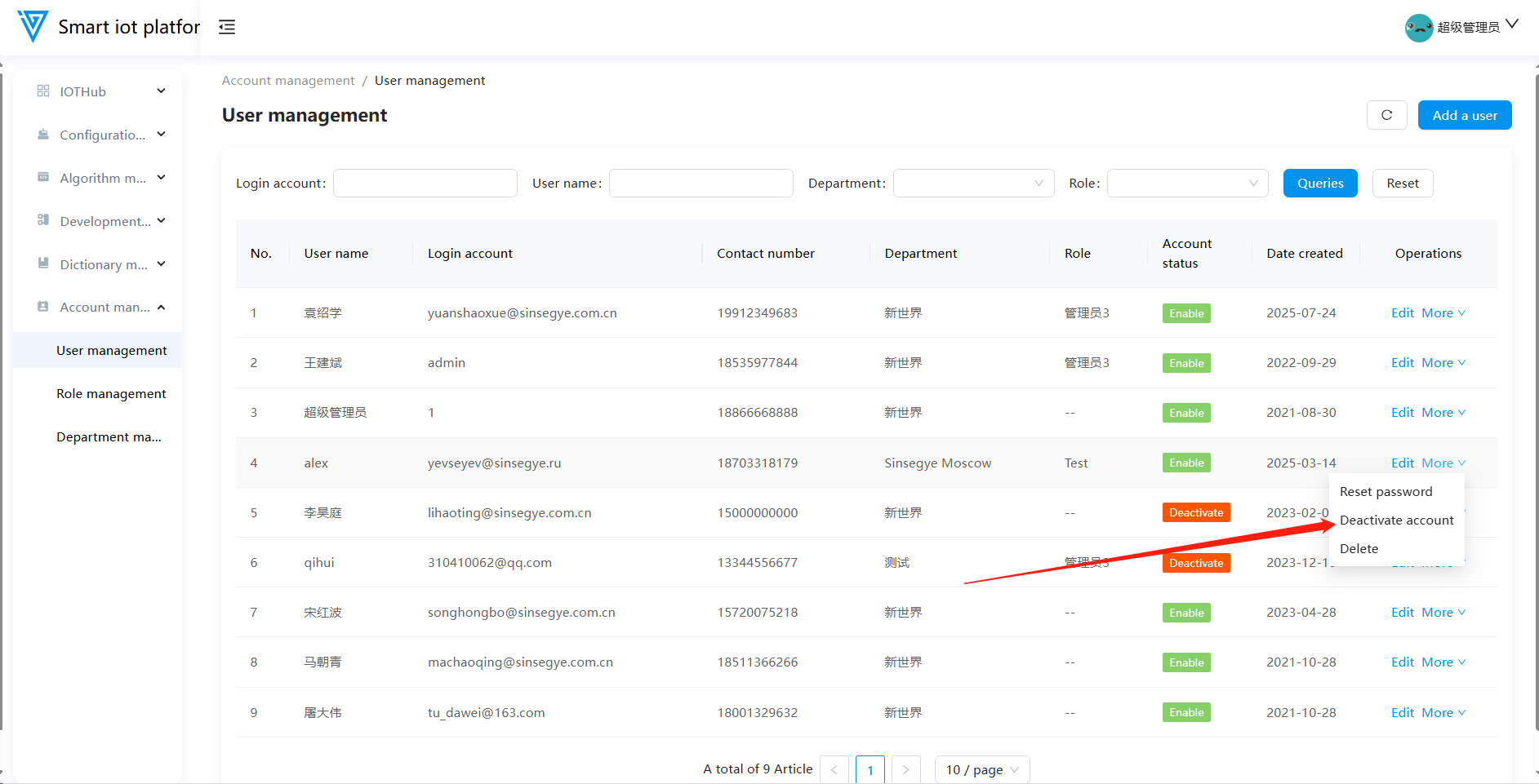
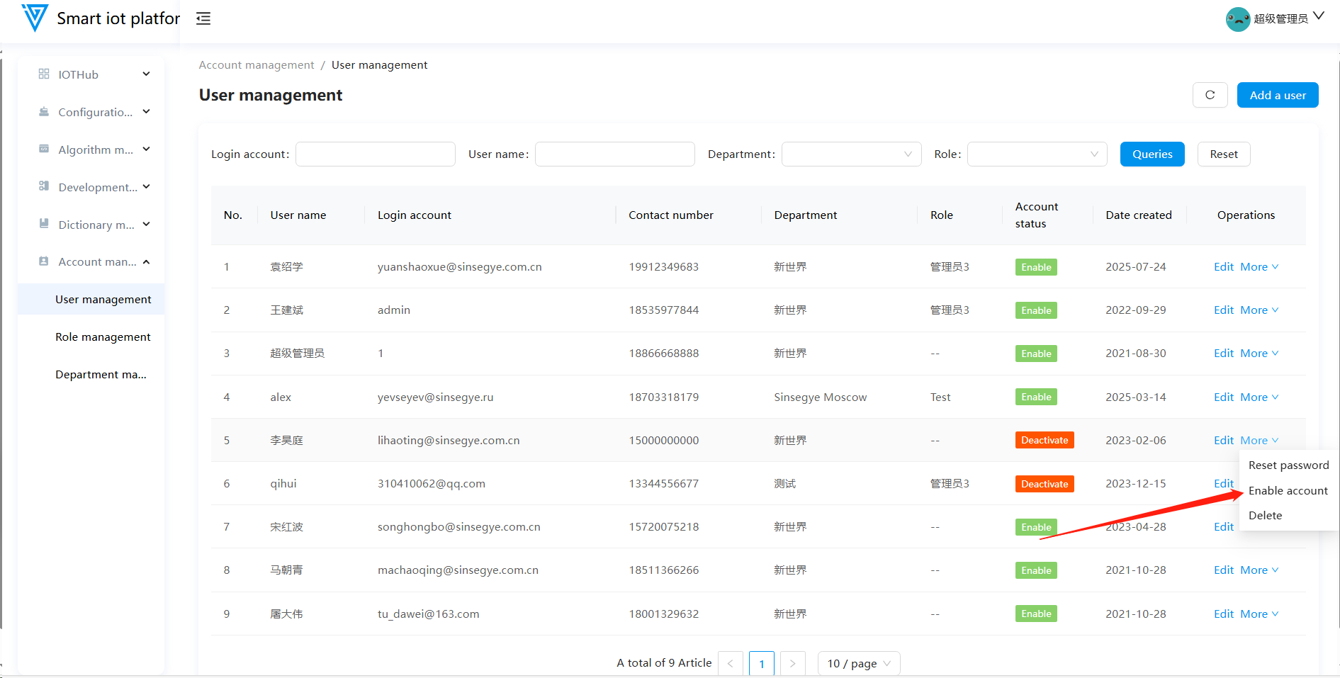
1.6 Enabling an Account
Disabled accounts can be re-enabled. Once enabled, the account's access rights are restored.
1.7 Deleting an Account
To delete a user, hover over the "More" button and click "Delete." After the confirmation pop-up appears, click "Confirm" to complete the deletion.
2. Role Management
2.1 Functional Overview
The Role Management module supports adding, editing, and deleting roles. Roles determine the scope of permissions for users assigned to them.
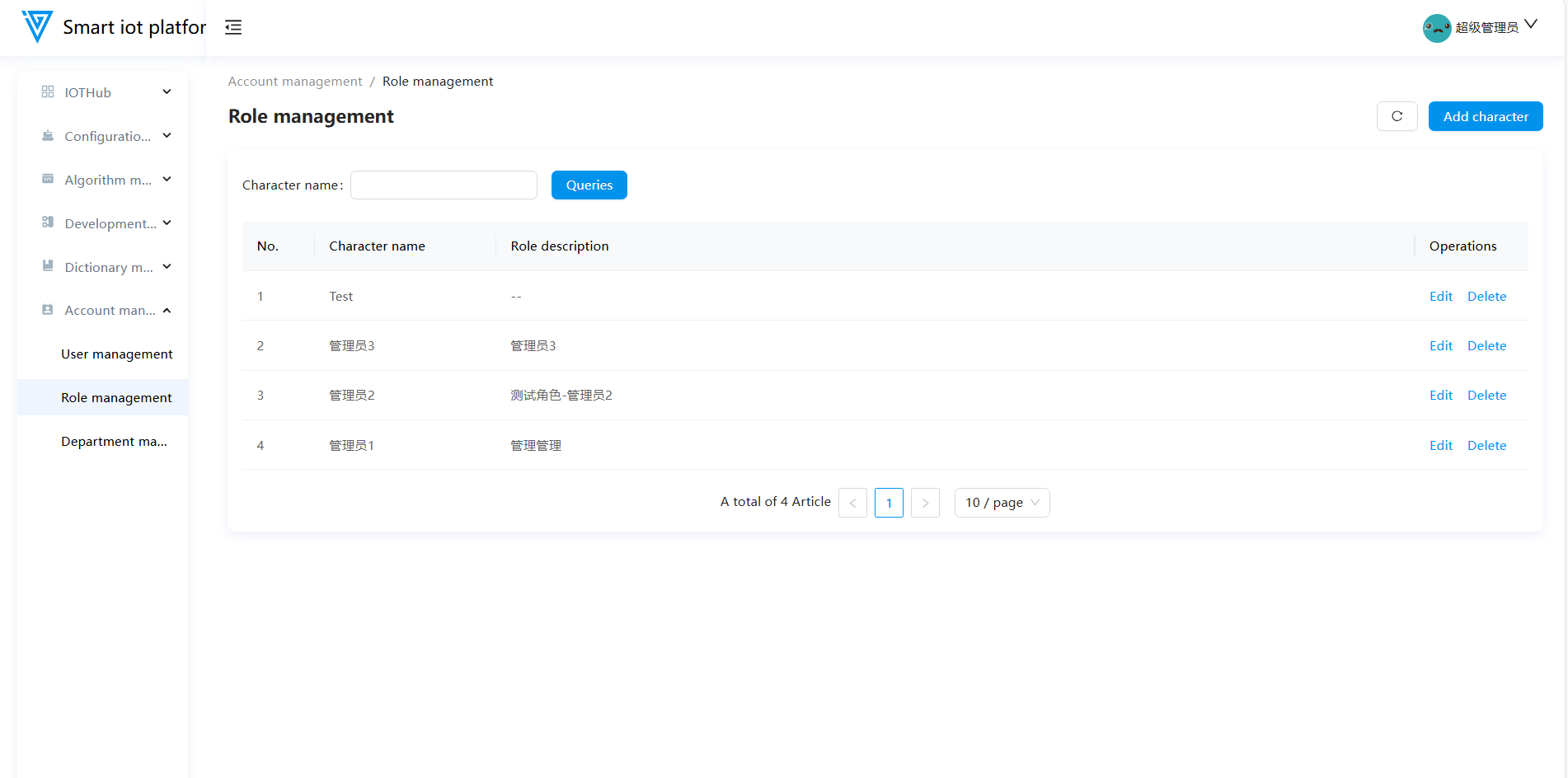
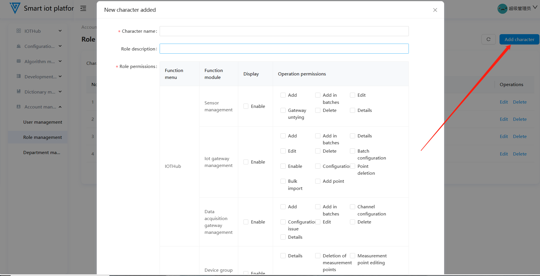
2.2 Adding a Role
Click the "Add Role" button in the upper right corner of the page to open the role addition pop-up window. Enter the role name, select the corresponding permissions, and click "Confirm" to complete the role addition.
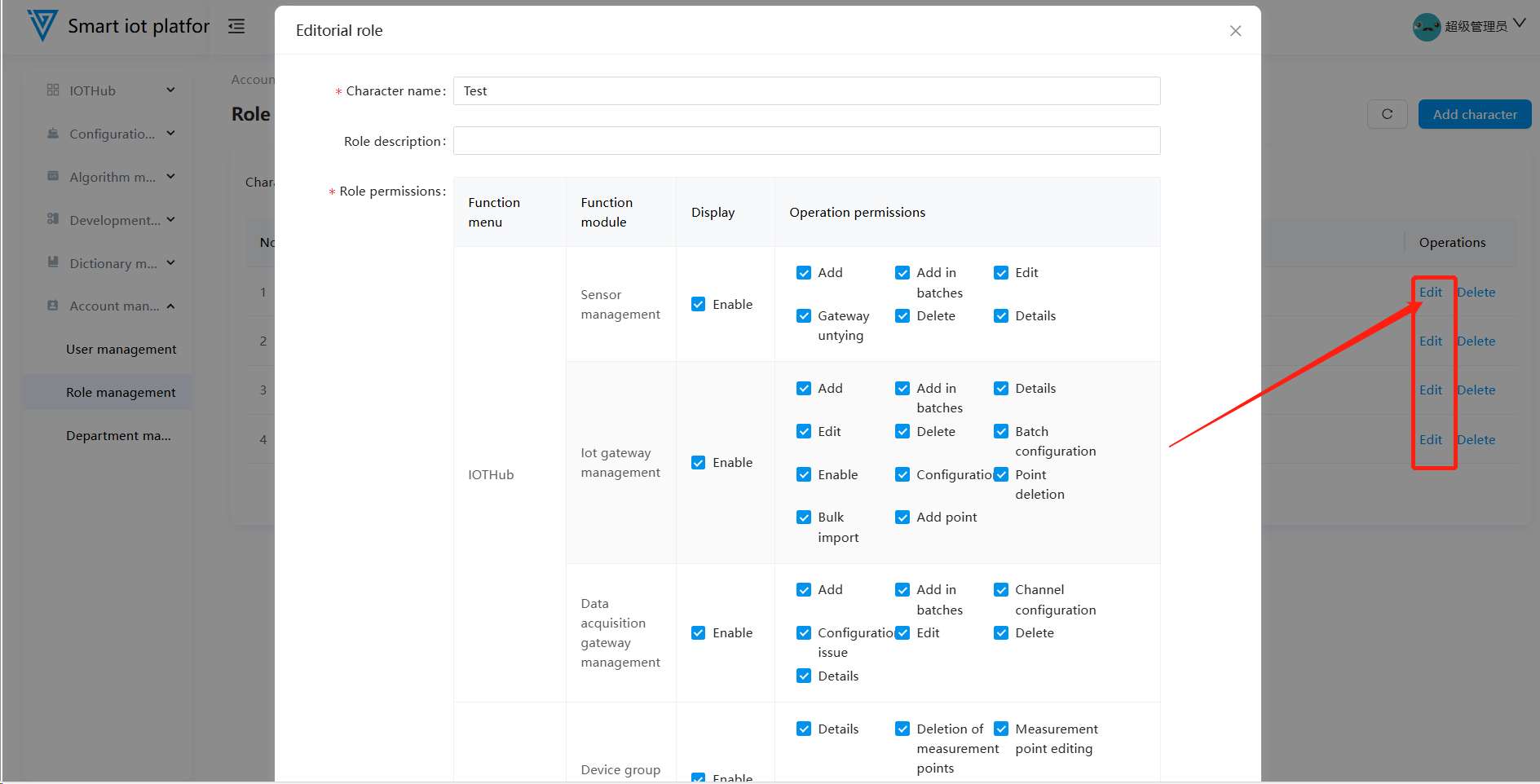
2.3 Editing a Role
To modify role permissions, click the "Edit" button on the page to enter the role editing pop-up window. After updating the permissions, click "Confirm" to save the changes.
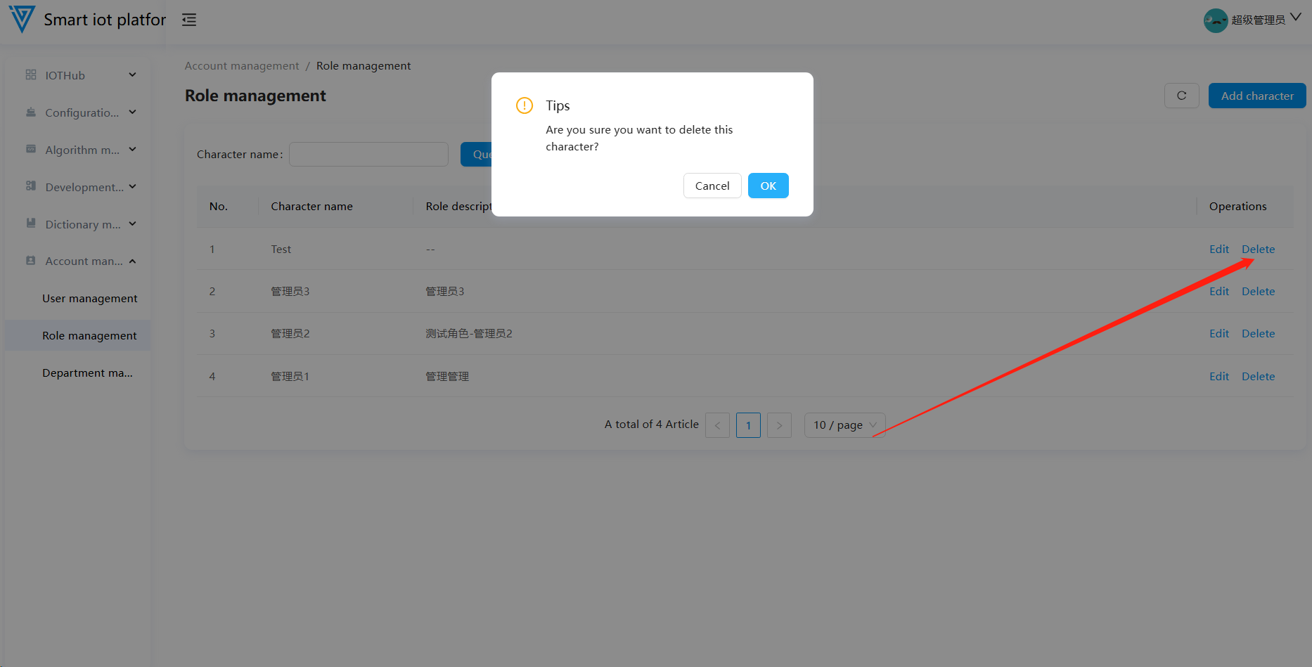
2.4 Deleting a Role
To delete an unnecessary role, click the "Delete" button on the page. After the confirmation pop-up appears, click "Confirm" to complete the deletion. Note: Roles that are already in use cannot be deleted.
3. Department Management
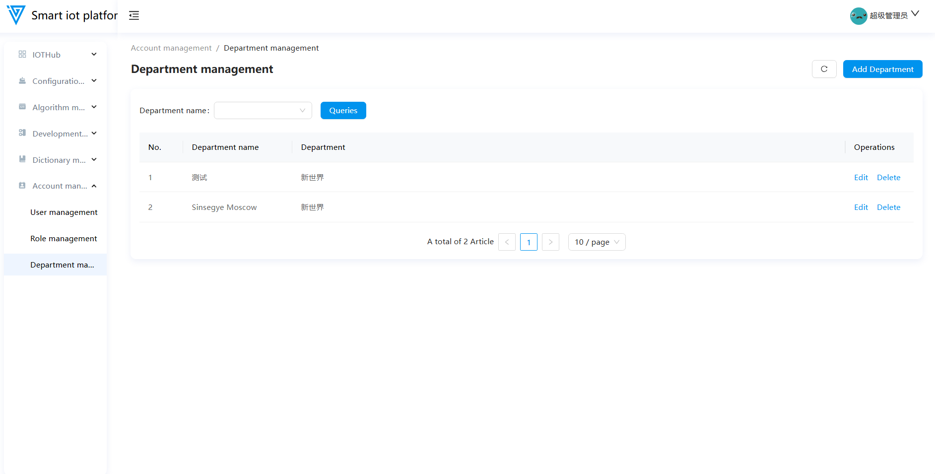
3.1 Functional Overview
The Department Management module supports adding, editing, and deleting departments.
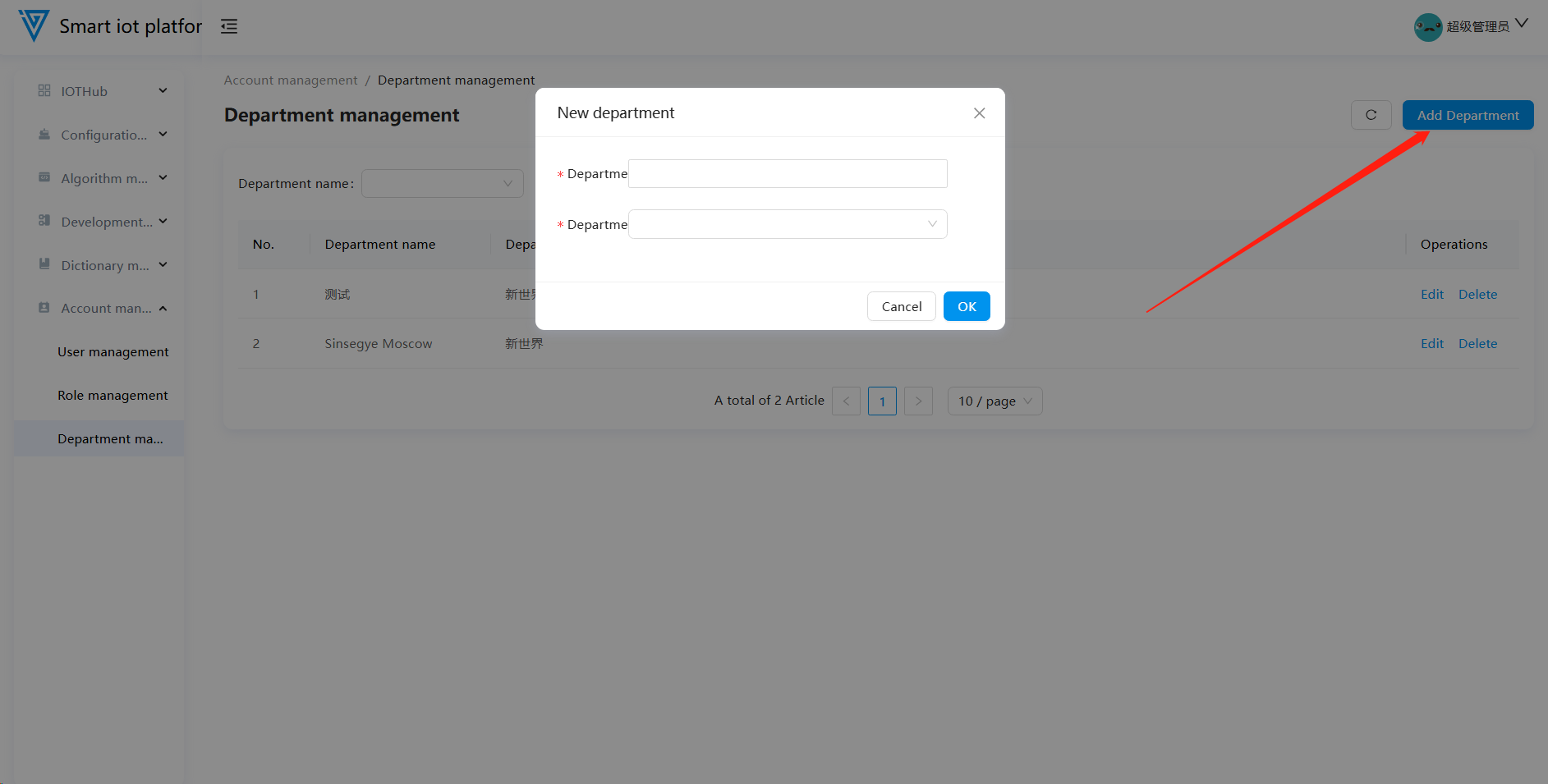
3.2 Adding a Department
Click the "Add Department" button in the upper right corner of the page to open the department addition pop-up window. Enter the department name and select the parent department (if applicable), then click "Confirm" to complete the addition.
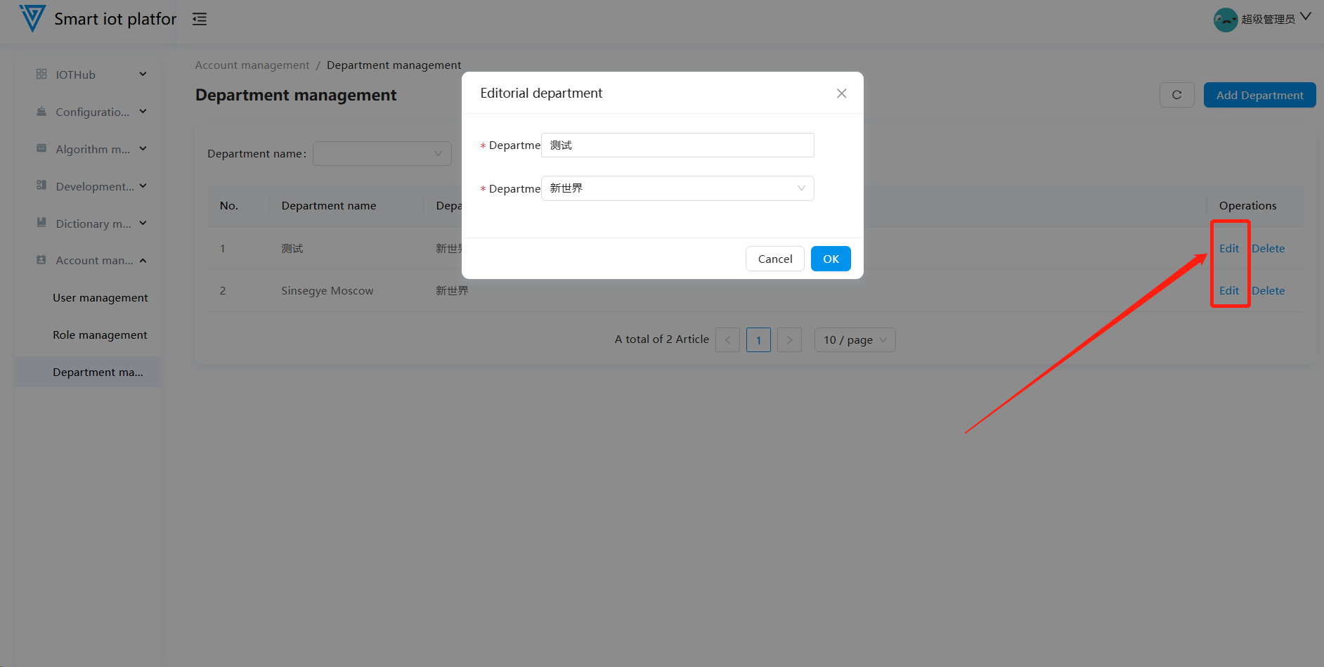
3.3 Editing a Department
Click the "Edit" button in the operation column to enter the department editing pop-up window. After updating the department information, click "Confirm" to save the changes.
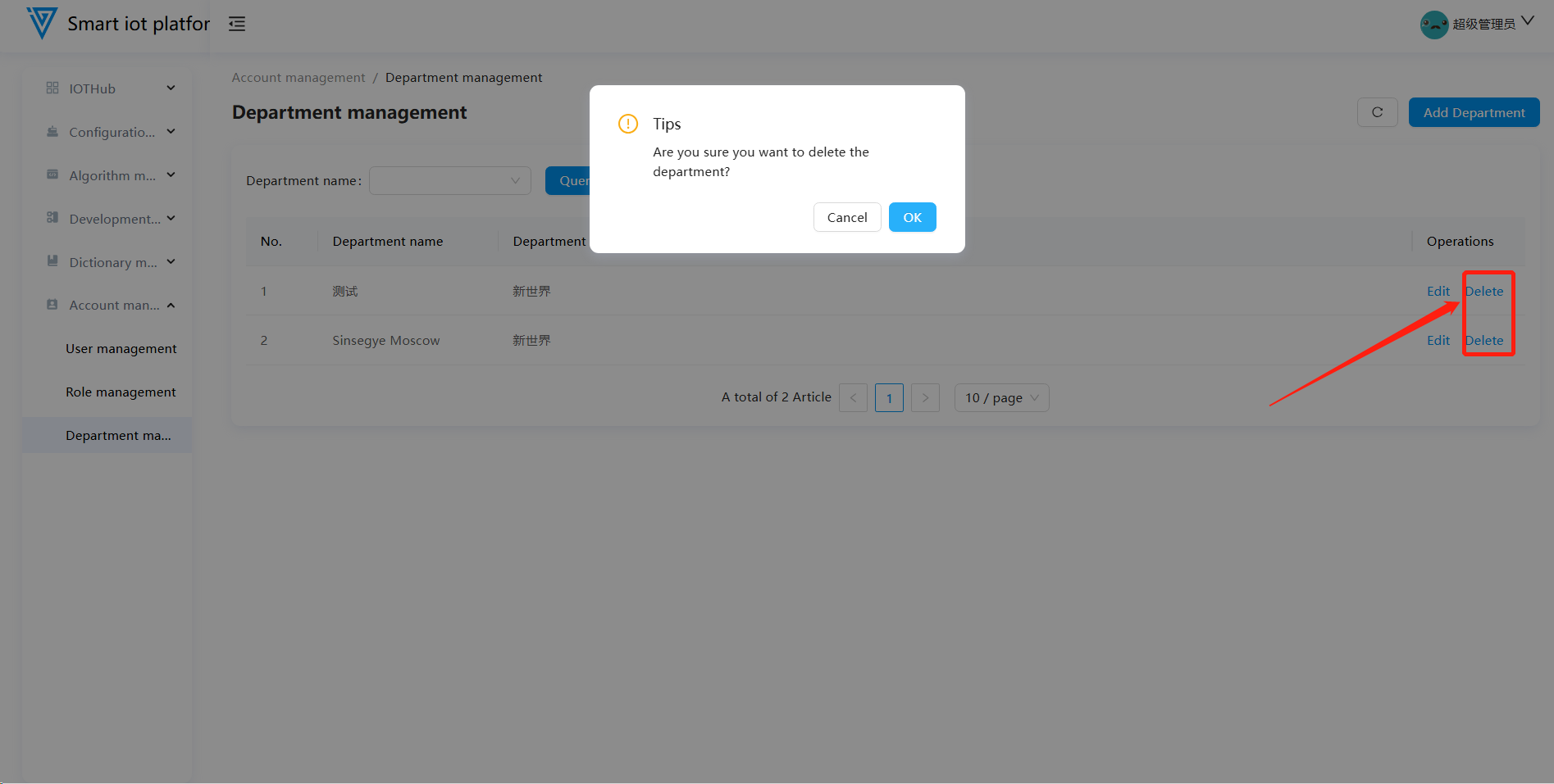
3.4 Deleting a Department
Click the "Delete" button on the page. After the confirmation pop-up appears, click "Confirm" to delete the department. Note: Departments with associated users cannot be deleted.