Modbus Rtu Master
Overview
Modbus itself is a specification for information exchange, and Modbus Rtu is a way to implement Modbus via serial ports. Therefore, all information is transmitted through serial ports; the Modbus protocol belongs to the C/S architecture, and the Modbus Rtu Master can read and write the addresses of Rtu Slaves to realize data interaction.
Application Scenarios
- Data collection and monitoring between devices (such as connection between PLCs, sensors, and HMIs).
- Data transmission in process automation.
- Remote monitoring and control systems.
Overall Architecture
Note: All Sinsegye software packages used in this manual can be obtained from the sub-pages of the official website. The version provided on the official website may be higher than the version mentioned in this manual. In general, this will not affect your execution of corresponding operations according to the examples in this manual.
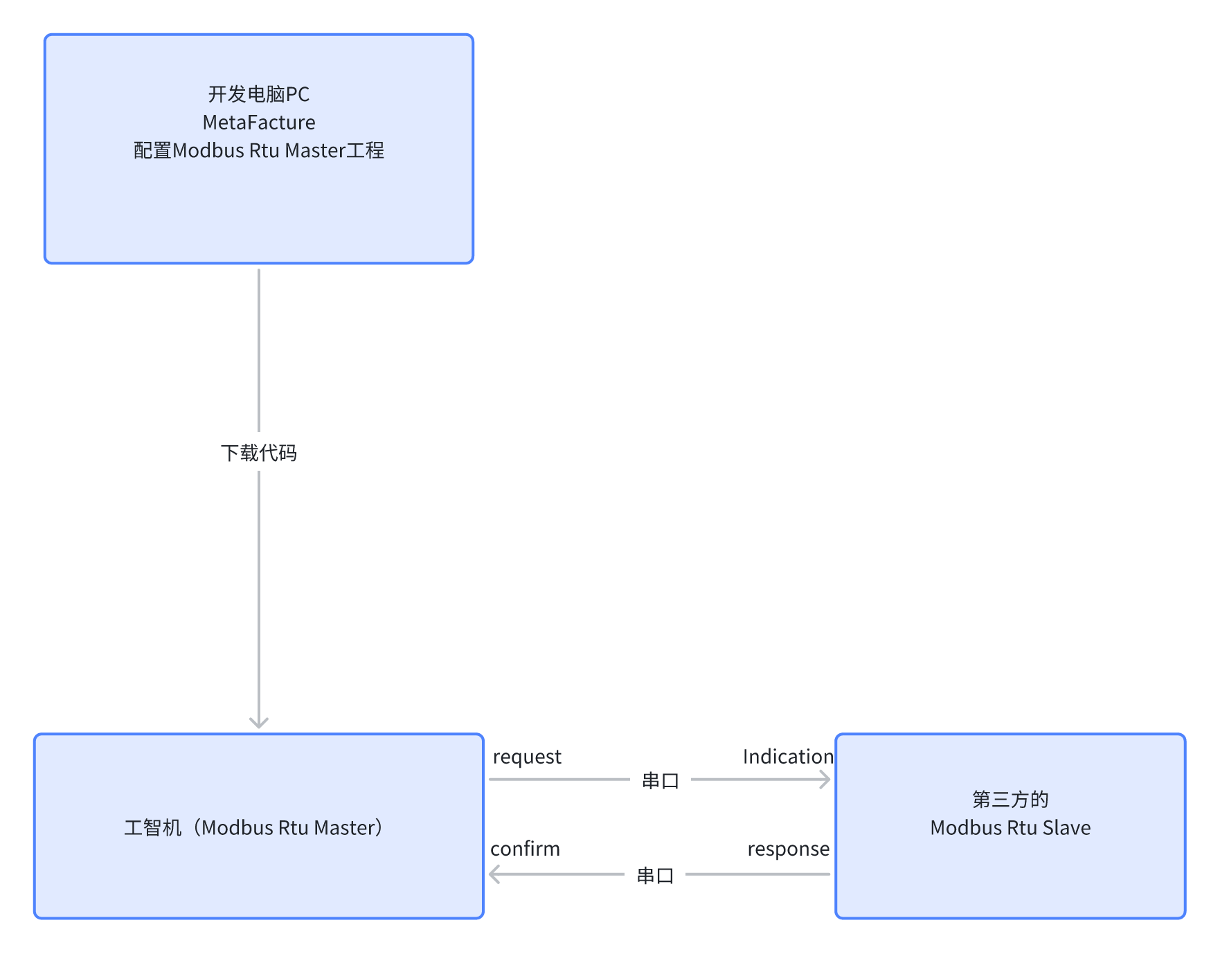
- Modbus Rtu is a way to implement Modbus via serial ports, so all messages are transmitted through serial ports. The Modbus Rtu Master can send read or write commands to the Rtu Slave, and the Rtu Slave will reply with confirmation information after receiving the command. The entire Modbus communication is based on the back-and-forth message exchange.
- The following table outlines each product component
| Product Component | Description |
|---|---|
| simodbusmaster_1.0.9_amd64.deb | Modbus Rtu Master RTE component |
| SF4100_ModbusMaster_1.0.0.2.library | Modbus Rtu Master Metafacture library file |
Installation and Uninstallation
Installation Requirements
- Sinsegye's factory-produced iComputer;
- Familiarity with basic Linux operation commands.
Installation Process
Installing Modbus Rtu Master RTE Component on iComputer
- Upload the deb package to the /home/sinsegye directory in the iComputer's Linux environment.
- After the upload is completed, execute the command on the iComputer to install (refer to the screenshot below; if the module file name changes, modify the file name in the command line accordingly).
- Modify the RTE configuration file, add simodbusmaster under the ComponentManager module.
- Restart the RTE service to make the newly added simodbusmaster take effect.
Installing the Library in Metafacture
-
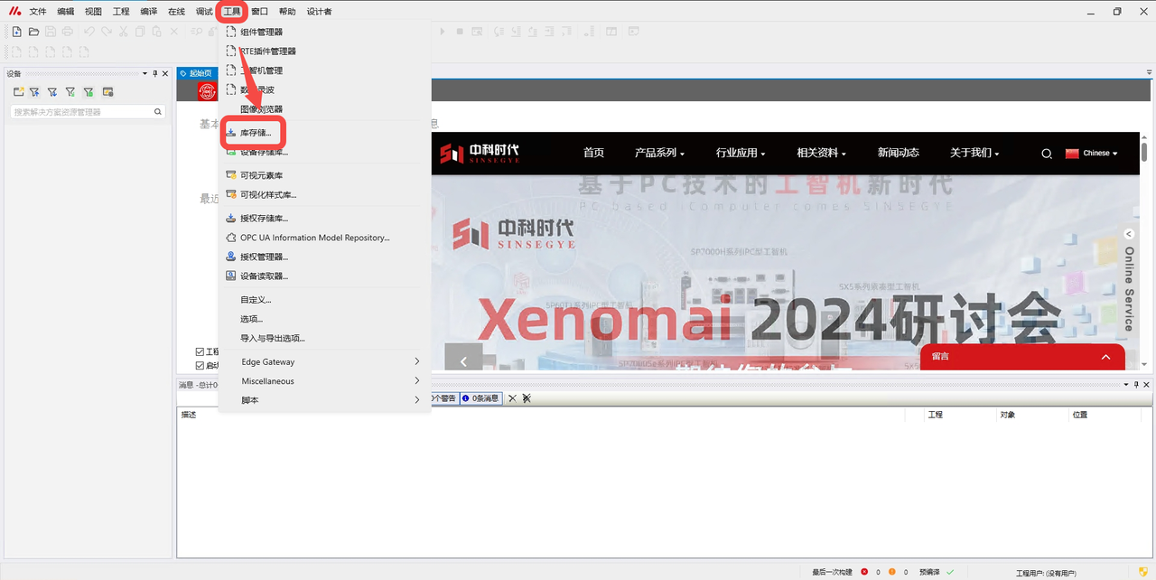
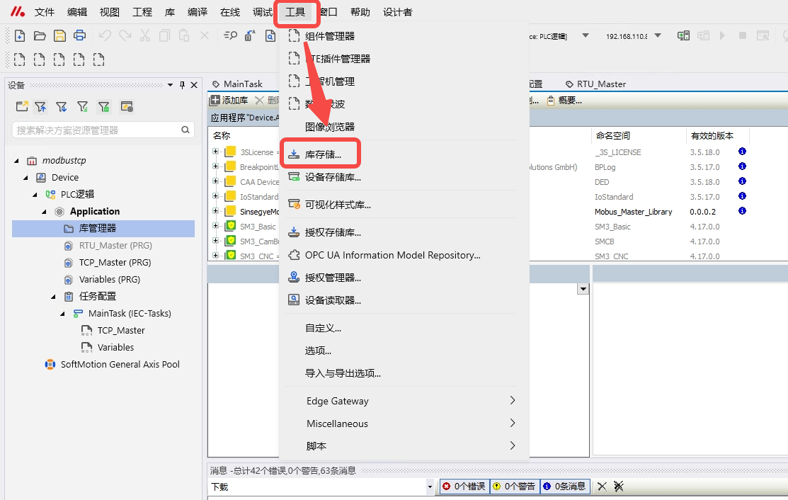
Open Metafacture, click "Tools" -- "Library Storage".
-
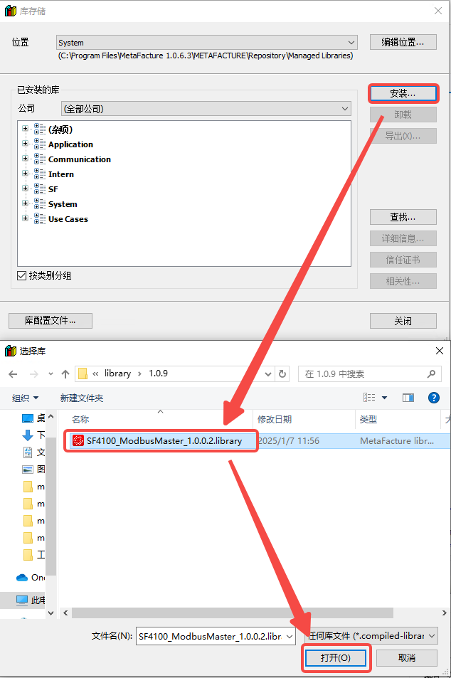
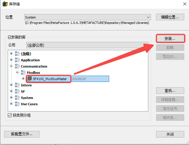
Click "Install" -- select the Modbus master library file, click "Open".
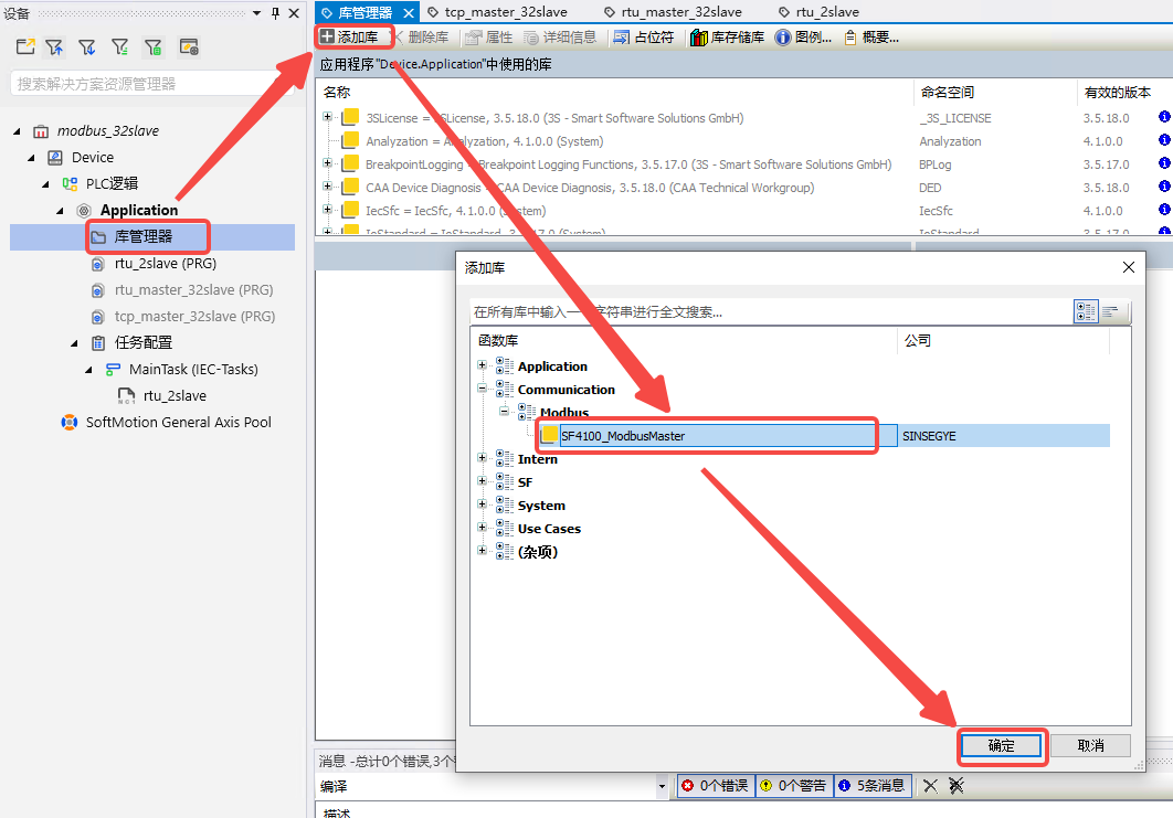
- In the project, click "Library Manager" -- "Add Library" -- select the Modbus library and click "OK".

Update Installation
Upgrading Modbus Rtu Master RTE Component on iComputer
- Upload the deb package to the /home/sinsegye directory in the iComputer's Linux environment.
- After the upload is completed, execute the command on the iComputer to install (refer to the screenshot below; if the module file name changes, modify the file name in the command line accordingly).
- Restart the RTE service to make the newly upgraded simodbusmaster take effect.
Upgrading the Library in Metafacture
-
Open Metafacture, click "Tools" -- "Library Storage".

-
Click "Install" -- select the new Modbus master library file, click "Open".
- In the project, click "Library Manager" -- "Add Library" -- select the new Modbus master library and click "OK".
Uninstallation Process
Uninstalling Modbus Rtu Master RTE Component on iComputer
- Execute the command on the iComputer to uninstall modbusmaster.
- Modify the RTE configuration file, remove simodbusmaster from the ComponentManager module.
- Restart the RTE service.
Uninstalling Modbus Rtu Master Library on MetaFacture Side
-
On the MetaFacture interface, click "Tools" -- "Library Storage".
-
In the dialog box, select the installed Modbus master library and click "Uninstall".
Technical Description
Quick Start
Software and Hardware Configuration in This Example
Hardware:
- SX5100 iComputer MetaOS V24.08.15_SX5
- Win10 PC
Software:
- MetaFacture V1.0.6.3
- Modbus slave tool
Experimental Requirements and Principles in This Example
- Experimental requirement: Configure the Modbus Rtu Master environment according to the "Installation Process" in the "Installation and Uninstallation" section.
Experimental Principle
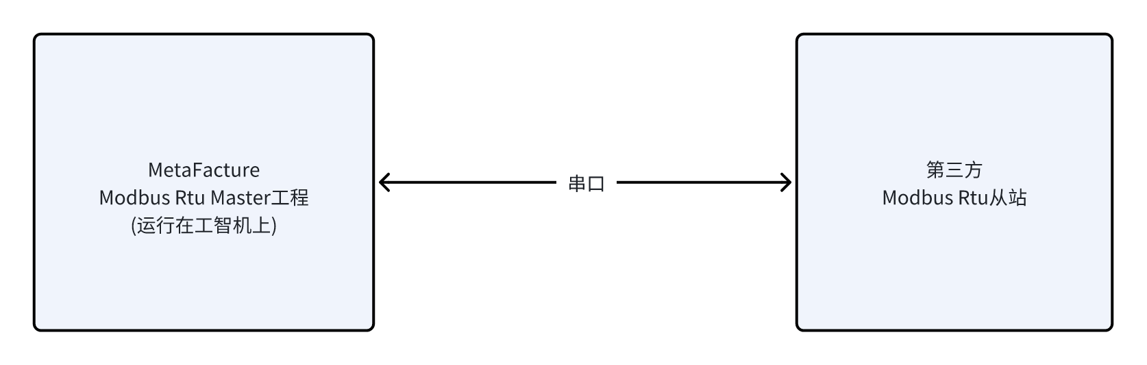
- The Metafacture Modbus Rtu station sends requests to the third-party Modbus Rtu slave through serial port connection, which mainly includes: function code, address and quantity of target registers, and data during write operations; after receiving the request, the slave first checks the validity of the data, then executes the requested operation and responds to the master's request.
- The upper computer and the iComputer are connected via EtherNet.
- On the upper computer, MetaFacture downloads the project to the iComputer. The project will include the configurations in the experimental operation steps below.
- The iComputer is connected to the third-party TCP/IP client via serial port.
Experimental Operation Steps in This Example
Steps for Master Initialization of Serial Port Experiment
- Call the Modbus Rtu Master serial port initialization function block in the declaration area of the POU.
- Call Fb_serialInit in the program area of the POU.
Steps for Reading Multiple Coils Experiment
- Call the Modbus Rtu Master function block for reading multiple coils in the declaration area of the POU.
- Call Fb_readCoils in the program area of the POU.
- After the project runs, trigger the rising edge of bExecute in Fb_readCoils to read the value of the coils.
Steps for Reading Discrete Inputs Experiment
- Call the Modbus Rtu Master function block for reading discrete inputs in the declaration area of the POU.
- Call Fb_readInputs in the program area of the POU.
- After the project runs, trigger the rising edge of bExecute in Fb_readInputs to read the value of the discrete inputs.
Steps for Reading Holding Registers Experiment
- Call the Modbus Rtu Master function block for reading holding registers in the declaration area of the POU.
- Call Fb_readRegs in the program area of the POU.
- After the project runs, trigger the rising edge of bExecute in Fb_readRegs to read the value of the holding registers.
Steps for Reading Input Registers Experiment
- Call the Modbus Rtu Master function block for reading input registers in the declaration area of the POU.
- Call Fb_readInputRegs in the program area of the POU.
- After the project runs, trigger the rising edge of bExecute in Fb_readInputRegs to read the value of the input registers.
Steps for Writing Multiple Coils Experiment
- Call the Modbus Rtu Master function block for writing multiple coils in the declaration area of the POU.
- Call Fb_writeCoils in the program area of the POU.
- After the project runs, trigger the rising edge of bExecute in Fb_writeCoils to write the value of the multiple coils.
Steps for Writing Multiple Holding Registers Experiment
- Call the Modbus Rtu Master function block for writing multiple holding registers in the declaration area of the POU.
- Call Fb_writeRegs in the program area of the POU.
- After the project runs, trigger the rising edge of bExecute in Fb_writeRegs to write the value of the multiple holding registers.
Steps for Writing Single Coil Experiment
- Call the Modbus Rtu Master function block for writing a single coil in the declaration area of the POU.
- Call Fb_writeSingleCoil in the program area of the POU.
- After the project runs, trigger the rising edge of bExecute in Fb_writeSingleCoil to write the single coil.
Steps for Writing Single Holding Register Experiment
- Call the Modbus Rtu Master function block for writing a single holding register in the declaration area of the POU.
- Call Fb_writeSingleReg in the program area of the POU.
- After the project runs, trigger the rising edge of bExecute in Fb_writeSingleReg to write the single holding register.
Experimental Notes
- The slave COM port used in the experiment is subject to the actual situation.
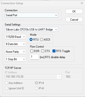
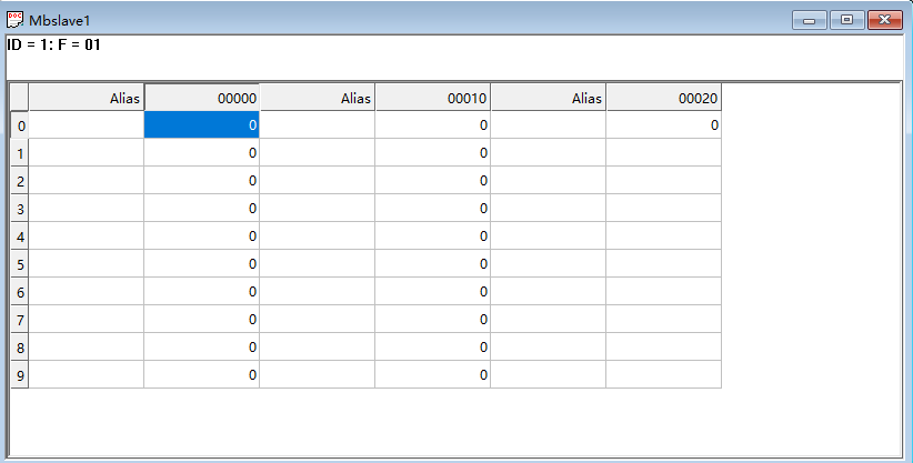
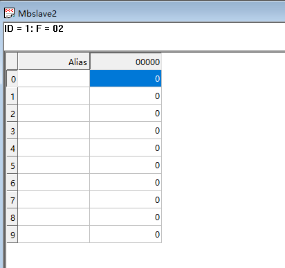
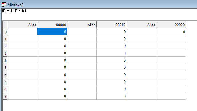
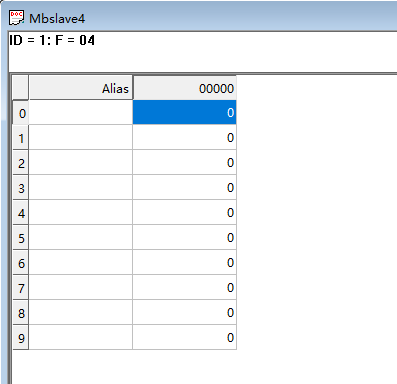
- The slave case used in the experiment is as follows:
-
The configuration of the slave COM port and serial port baud rate in Modbus Slave is subject to the actual situation:
-
Coil configuration: 21 bits
-
Discrete input configuration: 10 bits
-
Holding register configuration: 21 bits
-
Input register configuration: 10 bits
-
Function Introduction
Master Configuration: Initializing Serial Port
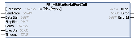
Introduction to Function Block FB_MBRtuSerialPortInit
Parameter Introduction
- Input Parameters
| Parameter Name | Parameter Type | Description |
|---|---|---|
| PortName | STRING | Serial port number |
| BaudRate | UINT | Baud rate setting; commonly used baud rates such as 9600, 38400, and 115200 are supported |
| DataBits | UINT | Data bits |
| StopBits | UINT | Stop bits |
| Parity | STRING | Parity bit |
| Execute | BOOL | Trigger execution |
| Timeout | TIME | Timeout |
- Output Parameters
| Parameter Name | Parameter Type | Description |
|---|---|---|
| BUSY | BOOL | Set when the function block is active until confirmation is received |
| Error | BOOL | Set to true if an error occurs during command transmission until the bBusy output is reset |
| ErrorId | UINT | Provides the error number when the bError output is set |
Master Configuration: Reading Multiple Coils from Slave
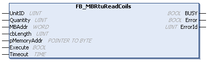
Introduction to Function Block FB_MBRtuReadCoils
Parameter Introduction
- Input Parameters
| Parameter Name | Parameter Type | Description |
|---|---|---|
| UnitID | UINT | ID of the slave |
| Quantity | UINT | Number of coils to read |
| MBAddr | WORD | Starting position of the coils to read |
| cbLength | UINT | Size of bytes to store the read data |
| pMemoryAddr | POINTER TO BYTE | Storage address of the data to be read |
| Execute | BOOL | Trigger the read action |
| tTimeout | Time | Timeout |
- Output Parameters
| Parameter Name | Parameter Type | Description |
|---|---|---|
| BUSY | BOOL | Set when the function block is active until confirmation is received |
| Error | BOOL | Set to true if an error occurs during command transmission until the bBusy output is reset |
| ErrorId | UINT | Provides the error number when the bError output is set |
Master Configuration: Reading Input Registers from Slave
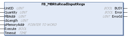
Introduction to Function Block FB_MBRtuReadInputRegs
Parameter Introduction
- Input Parameters
| Parameter Name | Parameter Type | Description |
|---|---|---|
| UnitID | UINT | ID of the slave |
| Quantity | UINT | Number of input registers to read; up to 125 at a time |
| MBAddr | UINT | Starting position of the input registers to read |
| cbLength | UINT | Size of bytes to store the read data |
| pMemoryAddr | POINTER TO BYTE | Storage address of the data to be read |
| Execute | BOOL | Trigger the read action |
| tTimeout | Time | Timeout |
- Output Parameters
| Parameter Name | Parameter Type | Description |
|---|---|---|
| BUSY | BOOL | Set when the function block is active until confirmation is received |
| Error | BOOL | Set to true if an error occurs during command transmission until the bBusy output is reset |
| ErrorId | UINT | Provides the error number when the bError output is set |
Master Configuration: Reading Discrete Inputs from Slave
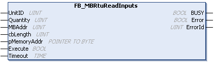
Introduction to Function Block FB_MBRtuReadInputs
Parameter Introduction
- Input Parameters
| Parameter Name | Parameter Type | Description |
|---|---|---|
| UnitID | UINT | ID of the slave |
| Quantity | UINT | Number of discrete inputs to read |
| MBAddr | UINT | Starting position of the discrete inputs to read |
| cbLength | UINT | Size of bytes to store the read data |
| pMemoryAddr | POINTER TO BYTE | Storage address of the data to be read |
| Execute | BOOL | Trigger the read action |
| tTimeout | Time | Timeout |
- Output Parameters
| Parameter Name | Parameter Type | Description |
|---|---|---|
| BUSY | BOOL | Set when the function block is active until confirmation is received |
| Error | BOOL | Set to true if an error occurs during command transmission until the bBusy output is reset |
| ErrorId | UINT | Provides the error number when the bError output is set |
Master Configuration: Reading Holding Registers from Slave
Introduction to Function Block FB_MBRtuReadRegs
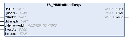
Parameter Introduction
- Input Parameters
| Parameter Name | Parameter Type | Description |
|---|---|---|
| UnitID | UINT | ID of the slave |
| Quantity | UINT | Number of holding registers to read; up to 125 at a time |
| MBAddr | UINT | Starting position of the holding registers to read |
| cbLength | UINT | Size of bytes to store the read data |
| pMemoryAddr | POINTER TO BYTE | Storage address of the data to be read |
| Execute | BOOL | Trigger the read action |
| tTimeout | Time | Timeout |
- Output Parameters
| Parameter Name | Parameter Type | Description |
|---|---|---|
| BUSY | BOOL | Set when the function block is active until confirmation is received |
| Error | BOOL | Set to true if an error occurs during command transmission until the bBusy output is reset |
| ErrorId | UINT | Provides the error number when the bError output is set |
Master Configuration: Writing Multiple Coils to Slave
Introduction to Function Block FB_MBRtuWriteCoils
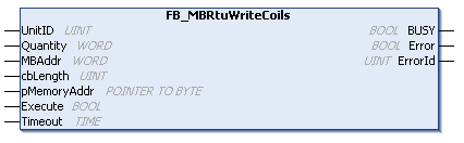
Parameter Introduction
- Input Parameters
| Parameter Name | Parameter Type | Description |
|---|---|---|
| UnitID | UINT | ID of the slave |
| Quantity | WORD | Number of coils to write |
| MBAddr | WORD | Starting position of the coils to write |
| cbLength | UINT | Size of bytes to store the written data |
| pMemoryAddr | POINTER TO BYTE | Address of the data to be written |
| Execute | BOOL | Trigger the write action |
| tTimeout | Time | Timeout |
- Output Parameters
| Parameter Name | Parameter Type | Description |
|---|---|---|
| BUSY | BOOL | Set when the function block is active until confirmation is received |
| Error | BOOL | Set to true if an error occurs during command transmission until the bBusy output is reset |
| ErrorId | UINT | Provides the error number when the bError output is set |
Master Configuration: Writing Multiple Holding Registers to Slave
Introduction to Function Block FB_MBRtuWriteRegs
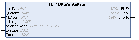
Parameter Introduction
- Input Parameters
| Parameter Name | Parameter Type | Description |
|---|---|---|
| UnitID | UINT | ID of the slave |
| Quantity | UINT | Number of holding registers to write |
| MBAddr | UINT | Starting position of the holding registers to write |
| pMemoryAddr | POINTER TO WORD | Address of the data to be written |
| Execute | BOOL | Trigger the write action |
| tTimeout | Time | Timeout |
- Output Parameters
| Parameter Name | Parameter Type | Description |
|---|---|---|
| BUSY | BOOL | Set when the function block is active until confirmation is received |
| Error | BOOL | Set to true if an error occurs during command transmission until the bBusy output is reset |
| ErrorId | UINT | Provides the error number when the bError output is set |
Master Configuration: Writing Single Coil to Slave
Introduction to Function Block FB_MBRtuWriteSingleCoil
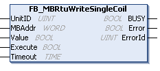
Parameter Introduction
- Input Parameters
| Parameter Name | Parameter Type | Description |
|---|---|---|
| UnitID | UINT | ID of the slave |
| MBAddr | WORD | Position of the coil to write |
| Value | BOOL | Value of the coil to write |
| Execute | BOOL | Trigger the write action |
| tTimeout | Time | Timeout |
- Output Parameters
| Parameter Name | Parameter Type | Description |
|---|---|---|
| BUSY | BOOL | Set when the function block is active until confirmation is received |
| Error | BOOL | Set to true if an error occurs during command transmission until the bBusy output is reset |
| ErrorId | UINT | Provides the error number when the bError output is set |
Master Configuration: Writing Single Holding Register to Slave
Introduction to Function Block FB_MBRtuWriteSingleReg
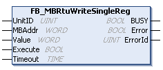
Parameter Introduction
- Input Parameters
| Parameter Name | Parameter Type | Description |
|---|---|---|
| UnitID | UINT | ID of the slave |
| MBAddr | WORD | Position of the holding register to write |
| Value | WORD | Value of the holding register to write |
| Execute | BOOL | Trigger the write action |
| tTimeout | Time | Timeout |
- Output Parameters
| Parameter Name | Parameter Type | Description |
|---|---|---|
| BUSY | BOOL | Set when the function block is active until confirmation is received |
| Error | BOOL | Set to true if an error occurs during command transmission until the bBusy output is reset |
| ErrorId | UINT | Provides the error number when the bError output is set |
Master Configuration: Connecting 32 Slaves
-
Use simulation software to configure 32 RTU slaves (each with a different slave ID), refer to the following:
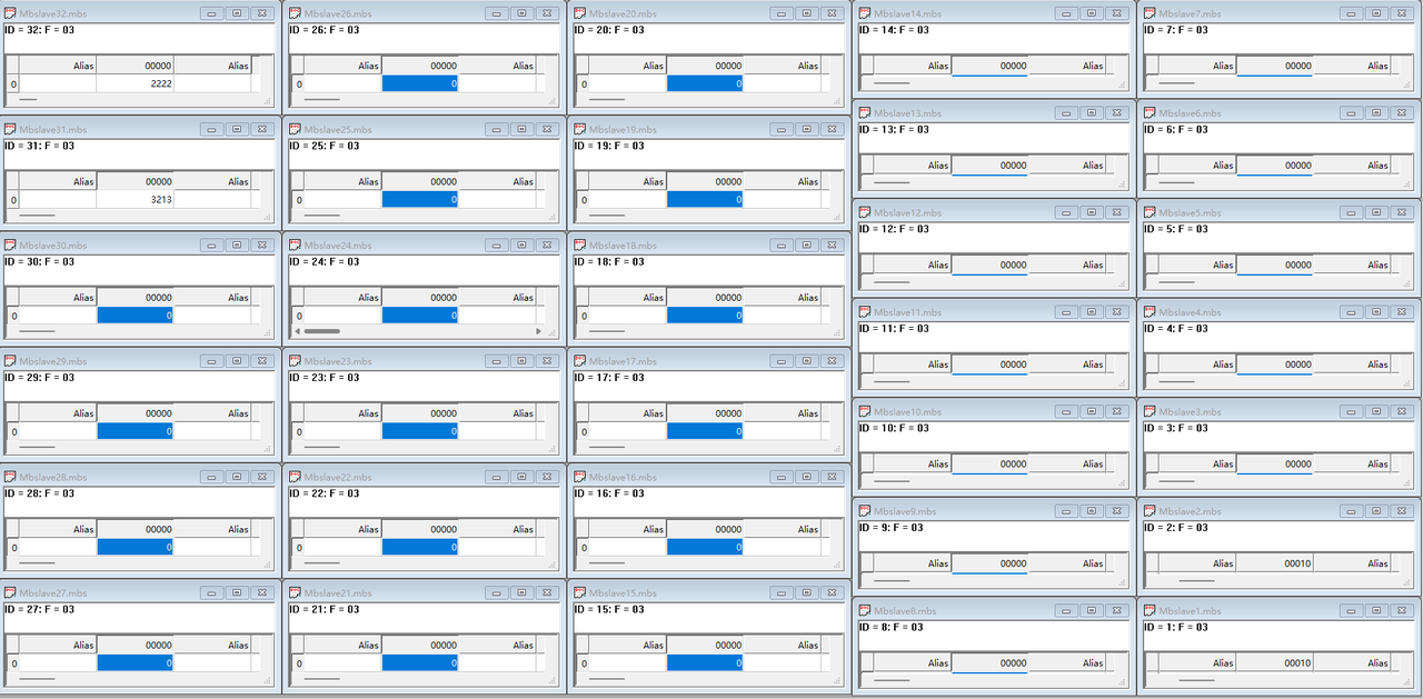
-
Configure the master project to connect to 32 slaves for read and write operations, and test that reading and writing work normally.
Error Handling
- If the serial port is not connected or the slave address requested by the master does not exist, the Error of the function block will be set to True after the project runs.
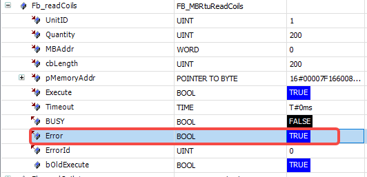
- It is necessary to first confirm that the serial port communication is normal, and then confirm that all slave addresses requested by the master exist.