Menu
Wiring Diagram
Wiring Diagram
SRL5012 Wiring Diagram
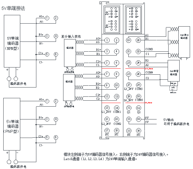
Note: Q1~Q2 are NPN output channels. The wiring example in the diagram only represents differential and single-ended connection, but does not mean that each channel can only be limited to the connection in the diagram.
SRL5034 Wiring Diagram
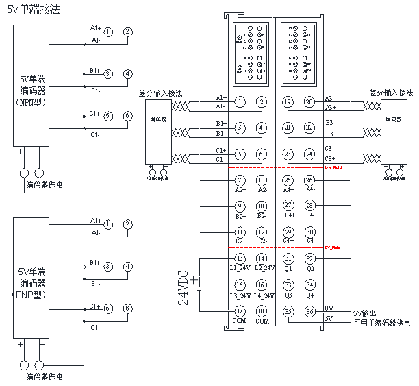
Note: L1, L2, L3 and L4 are 24V single-ended input channels, and Q1~Q4 are NPN output channels. The wiring example in the diagram only represents differential and single-ended connection, but does not mean that each channel can only be limited to the connection in the diagram.
Module Terminal Description
SRL5012 Terminal Description
| Terminal | Meaning |
|---|---|
| A1+/A1- | Channel 1, Phase A input terminal |
| B1+/B1- | Channel 1, Phase B input terminal |
| C1+/C1- | Channel 1, Phase C input terminal |
| L1_24V/COM1 | LATCH1 input terminal |
| A2+/A2- | Channel 2, Phase A input terminal |
| B2+/B2- | Channel 2, Phase B input terminal |
| C2+/C2- | Channel 2, Phase C input terminal |
| L2_24V/COM2 | LATCH2 input terminal |
| A1 | Channel 1, Phase A input terminal |
| B1 | Channel 1, Phase B input terminal |
| C1 | Channel 1, Phase C input terminal |
| COM3 | Channel 1, Phases A, B, and C input COM |
| A2 | Channel 2, Phase A input terminal |
| B2 | Channel 2, Phase B input terminal |
| C2 | Channel 2, Phase C input terminal |
| COM4 | Channel 2, Phases A, B, and C input COM |
| L_24V/COM5 | LATCH3 input terminal |
| L_24V/COM6 | LATCH4 input terminal |
| Q1 | Channel 1 Gated Output, NPN |
| Q2 | Channel 2 Gated Output, NPN |
| 5V/0V | 5V DC power output terminal. |
SRL5034 Terminal Description
| Terminal | Meaning |
|---|---|
| A1+/A1- | Channel 1, Phase A differential input |
| B1+/B1- | Channel 1, Phase B differential input |
| C1+/C1- | Channel 1, Phase C differential input |
| A2+/A2- | Channel 2, Phase A differential input |
| B2+/B2- | Channel 2, Phase B differential input |
| C2+/C2- | Channel 2, Phase C differential input |
| A3+/A3- | Channel 3, Phase A differential input |
| B3+/B3- | Channel 3, Phase B differential input |
| C3+/C3- | Channel 3, Phase C differential input |
| A4+/A4- | Channel 4, Phase A differential input |
| B4+/B4- | Channel 4, Phase B differential input |
| C4+/C4- | Channel 4, Phase C differential input |
| L1_24V | LATCH1 input terminal |
| L2_24V | LATCH2 input terminal |
| L3_24V | LATCH3 input terminal |
| L4_24V | LATCH4 input terminal |
| COM | LATCH input COM |
| 5V/0V | 5V DC power output terminal. |
| Q1 | Channel 1 Gated Output, NPN |
| Q2 | Channel 2 Gated Output, NPN |
| Q3 | Channel 3 Gated Output, NPN |
| Q4 | Channel 4 Gated Output, NPN |
Share this Article
Last modified: 2025-06-30
- MetaOS Overview
- How to log in and view the system
- How to modify the system language
- How to set network port IP using command line method
- How to set real-time domain system time, non real time domain system time, and hardware time
- How to check the status of PLC
- How to check the status of system resources
- How to view system logs
- How to set system memory
- How to allocate system CPU
- How to allocate system network ports
- How to use the command line to set NIC interrupts
- Chapter 1: Installation and Uninstallation
- Chapter 2: Set the user interface language to Simplified Chinese
- Chapter 3: New Construction
- Chapter 4: Open Project
- Chapter 5: Add / Delete / Export Devices
- Chapter 6: Connecting to PLC
- Chapter 7: Connecting MetaFacture PLC Simulator
- Chapter 8: Downloading and Uploading Projects
- Chapter 9: Scanning Devices
- Chapter 10: Installing and Using Libraries
- Safety tips for unpacking acceptance
- Safety tips for storage and transport
- Safety tips during assembly
- Safety tips for equipment wiring
- Safety tips for equipment power-on
- Safety tips for equipment operation
- Safety tips for equipment maintenance
- Safety tips for equipment repair
- Safety tips for equipment recycling
- Technical Specifications
- Troubleshooting and Disposal
- Expansion Module
- Appendix
- Safety tips for unpacking acceptance
- Safety tips for storage and transport
- Safety tips during assembly
- Safety tips for equipment wiring
- Safety tips for equipment power-on
- Safety tips for equipment operation
- Safety tips for equipment maintenance
- Safety tips for equipment repair
- Safety tips for equipment recycling
- Product overview
- Technical Specifications
- Troubleshooting and Disposal
- Care and Maintenance
- Appendix
- Safety tips for unpacking acceptance
- Safety tips for storage and transport
- Safety tips during assembly
- Safety tips for equipment wiring
- Safety tips for equipment power-on
- Safety tips for equipment operation
- Safety tips for equipment maintenance
- Safety tips for equipment repair
- Safety tips for equipment recycling
- Object Dictionary
- SV35 Profinet Series AC Servo Driver
- Safety tips for unpacking acceptance
- Safety tips for storage and transport
- Safety tips during assembly
- Safety tips for equipment wiring
- Safety tips for equipment power-on
- Safety tips for equipment operation
- Safety tips for equipment maintenance
- Safety tips for equipment repair
- Safety tips for equipment recycling
- Product Overview
- Technical Specifications
- Motor