SF5182 ZKSDTempControl
Overview
ZKSDTempControl is an algorithm library for temperature control, also referred to as a temperature controller. The controller can operate in automatic mode (closed-loop) and manual mode (open-loop).
The output of the controller can be digital or analog, and the digital control value is pulse-width modulated (PWM). It also supports two-point or three-point output. The control value is limited between the allowed minimum and maximum values.
The setpoint is limited between the allowed minimum and maximum values and can also be a ramp input. Through the interface of the function block, the setpoint can be switched to the standby setpoint. The soft start function can be parameterized to support the "heater baking" operation. This process includes: the setpoint (optionally adjusted by a ramp) is initially set to a lower value, maintained at that value for a certain period of time, and then changed to the target setpoint (optionally adjusted by a ramp).
The actual value can be digitally filtered.
The control algorithm is based on the PID (Proportional-Integral-Derivative) principle and can be supplemented with a feedforward controller to minimize overshoot.
The following table outlines each product component:
| Product Component | Description |
|---|---|
| FB_CTRL_Selftunner | Self-tuning algorithm |
| FB_CTRL_ControlAlgorithm | Control algorithm |
| FB_CTRL_SetPointConditioner | Setpoint generator |
| FB_CTRL_ControlValueConditioner | Control value generator |
| FB_Alarming | Alarm |
Installation and Uninstallation
Installation Requirements
This section describes the minimum requirements for the engineering and/or runtime system.
1. Hardware Requirements
Devices supporting the MetaFacture platform (PLC or embedded systems).
2. Software Requirements
Installed MetaFacture development environment.
Operating system support: MetaOS or other compatible platforms.
Relevant library or module dependencies must be available (such as basic I/O libraries).
Installation Process
Open the engineering project in MetaFacture.
Select "Tools" -> "Library Storage" via the menu.
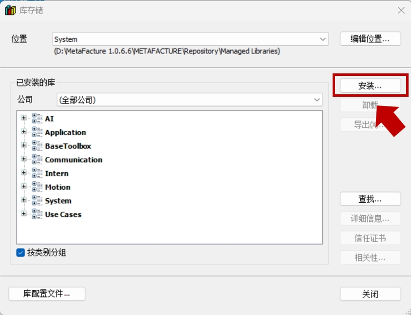
Click install and open the ZKSDTempControl.compiled-library file.
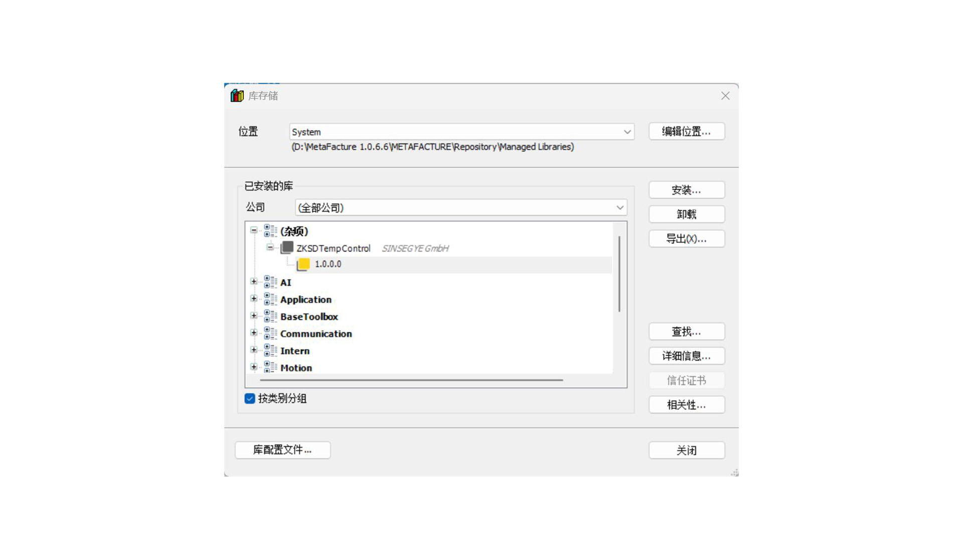
After successful opening, close the window.
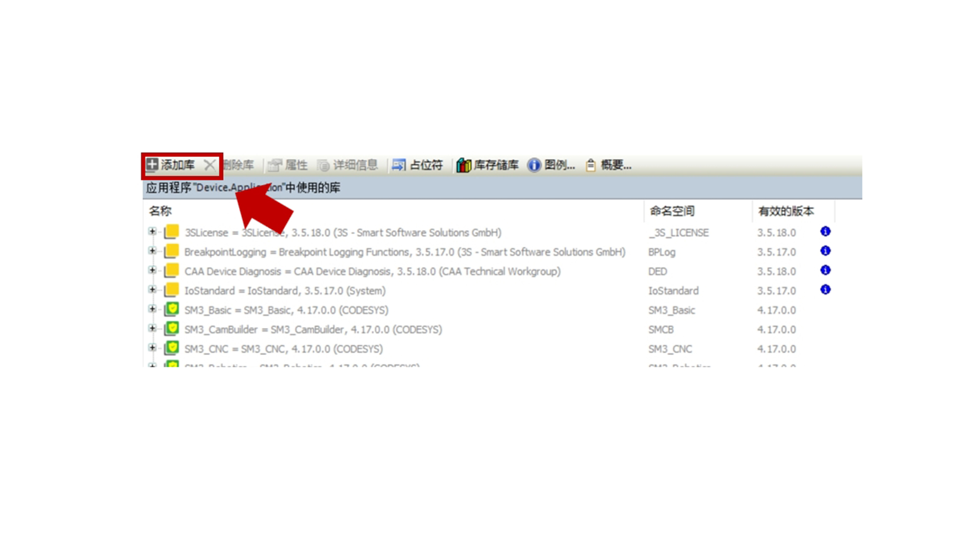
Click "Add Library"
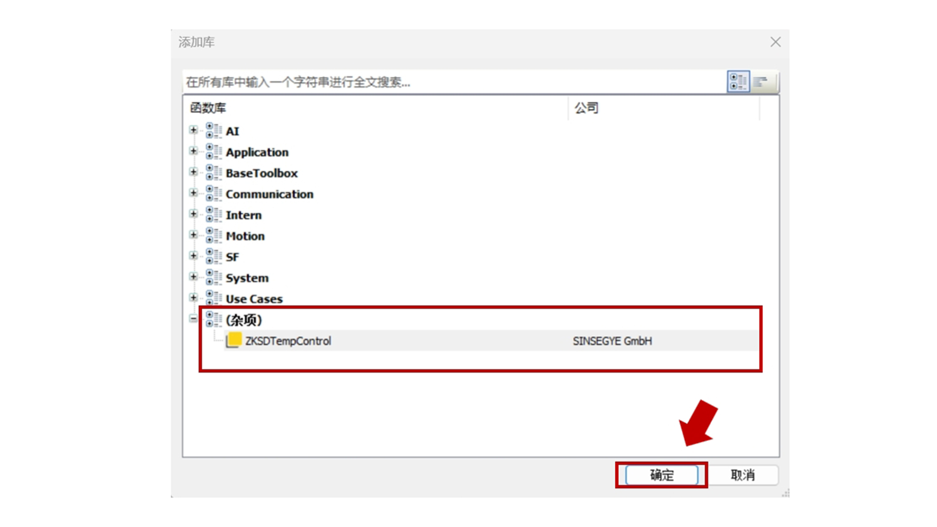
Select ZKSDTempControl and click confirm.
Update Installation
1. Overwrite Installation
Download the latest version of the ZKSDTempControl library file.
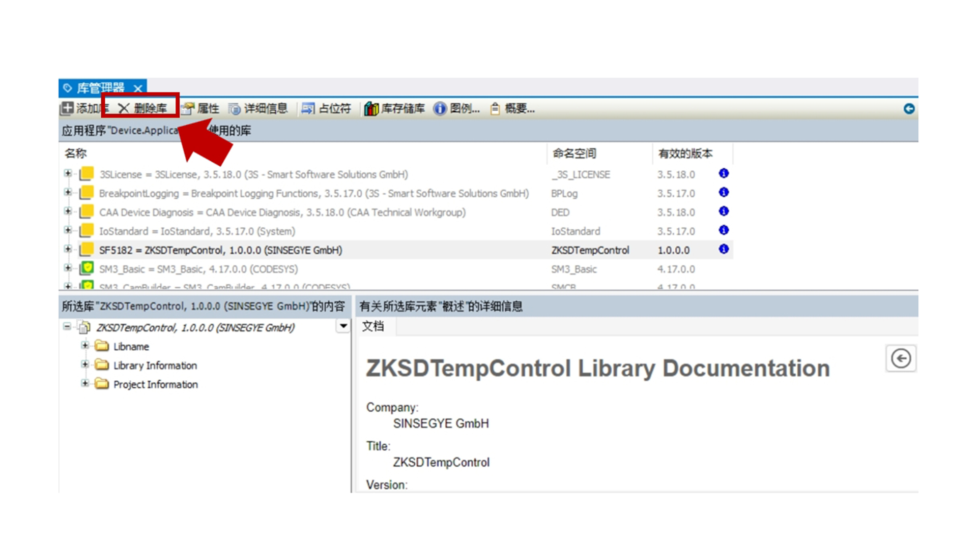
Open the MetaFacture project, delete the old version of the library in the "Library Manager", and import the new version of the library file.
Save the project and recompile.
2. Version Compatibility Verification
Check whether the new version is compatible with the existing project.
Adjust possible differences between the old and new versions according to the documentation.
Uninstallation Process
1. Uninstallation via Library Manager
Open the MetaFacture project and enter the "Library Manager".
Select the ZKSDTempControl library and click "Delete Library" to uninstall the library file.
- Clean Up Project Dependencies
Open the engineering project, check and remove all function blocks or interfaces that use the ZKSDTempControl library.
Ensure that the project compiles without errors after recompilation.
Function Introduction
Structure Diagram
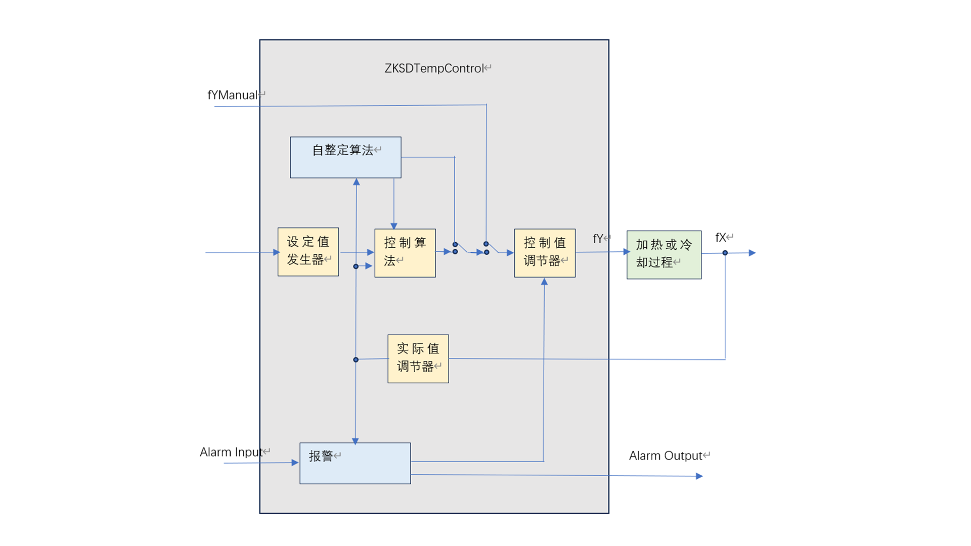
The temperature controller consists of the following function blocks:
-
Self-tuning algorithm (FB_CTRL_Selftunner)
-
Control algorithm (FB_CTRL_ControlAlgorithm)
-
Setpoint generator (FB_CTRL_SetPointConditioner)
-
Control value generator (FB_CTRL_ControlValueConditioner)
-
Alarm (FB_Alarming)
These function blocks call other auxiliary function blocks in sequence.
Setpoint Generator
The schematic diagram of the setpoint generator is shown below.
There are two set temperatures: the actual set temperature and the standby set temperature. The standby set temperature can be used to reduce the temperature to a lower value during heating pause to save power, also known as the heat preservation function. If necessary, the setpoint can be adjusted gradually according to the set ramp.
The setpoint is constrained by its limit range.
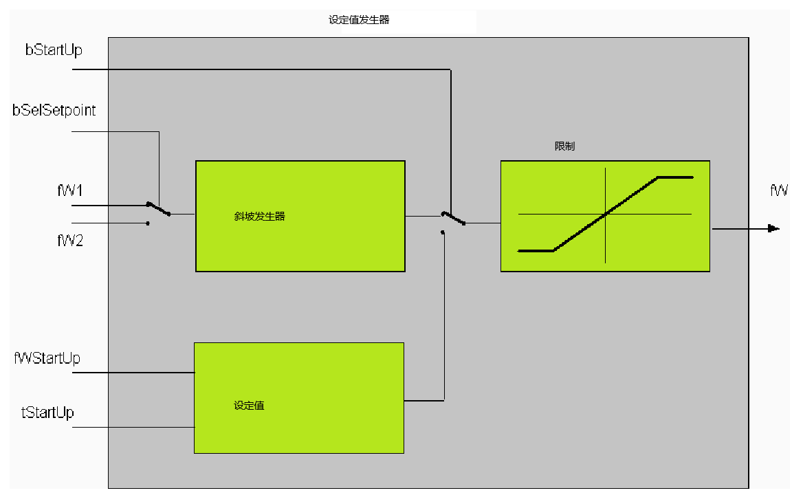
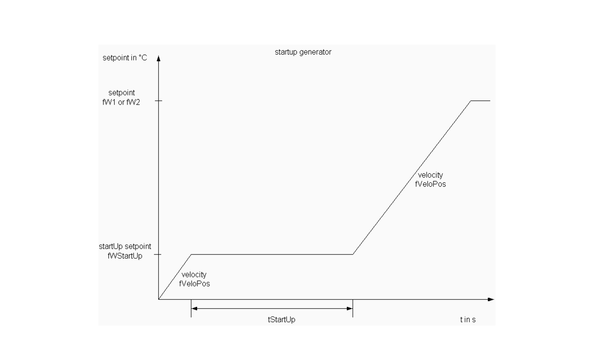
Parameterization can be performed when using the "Soft Start" function. When "Soft Start" is enabled, the temperature first rises from the ambient temperature to a low setpoint (fWStartUp), then maintains this temperature for a period of time (tStartUp), and then starts to rise to the actual setpoint.
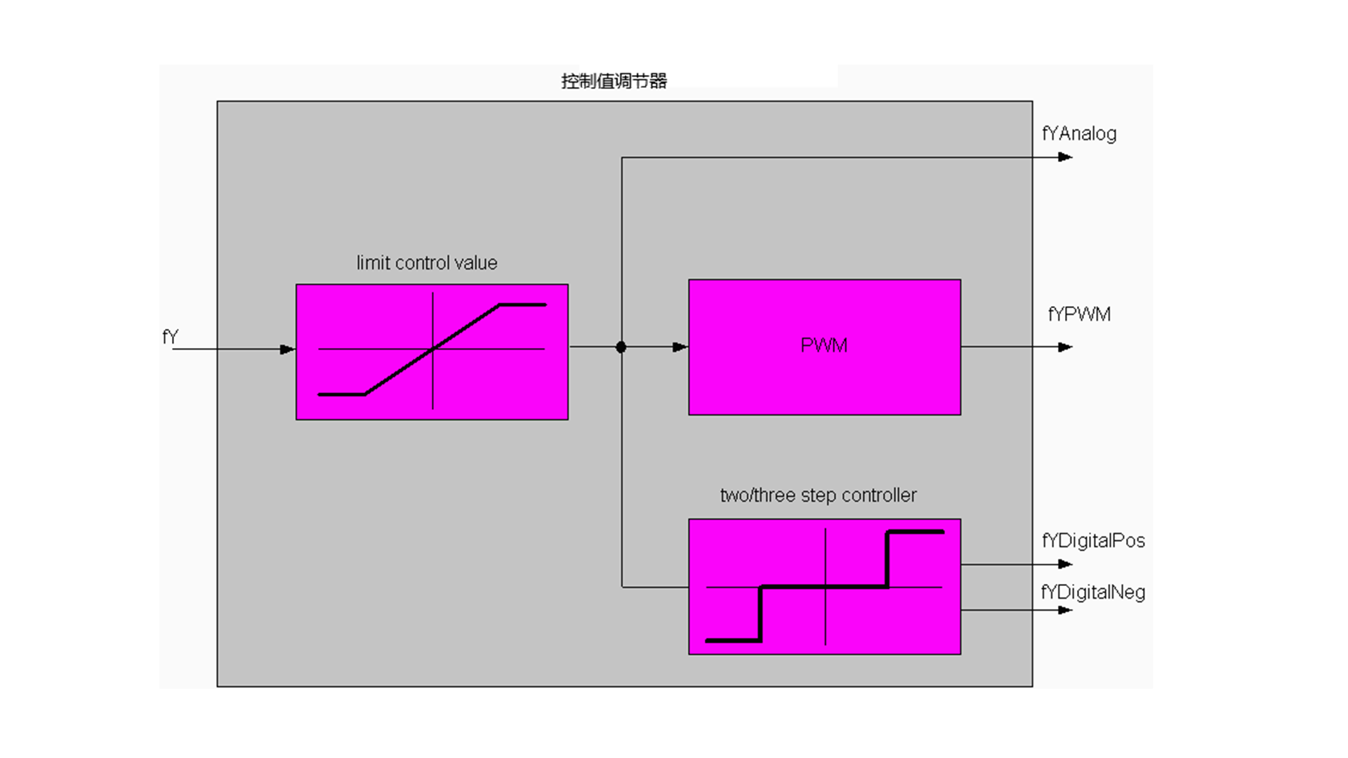
Control Value Conditioner
The control value calculated by the controller is first limited, and the limits are passed to the controller function block through the control value structure. The control value is provided in three different ways. The control value can be output in analog form. It can also be in the form of a pulse-width modulated signal with digital output. The cycle time required for pulse-width modulation is provided to the controller through the control value structure. In addition, two-point output (for heating or cooling) and three-point output (for heating or cooling) can be connected.
Control Algorithm
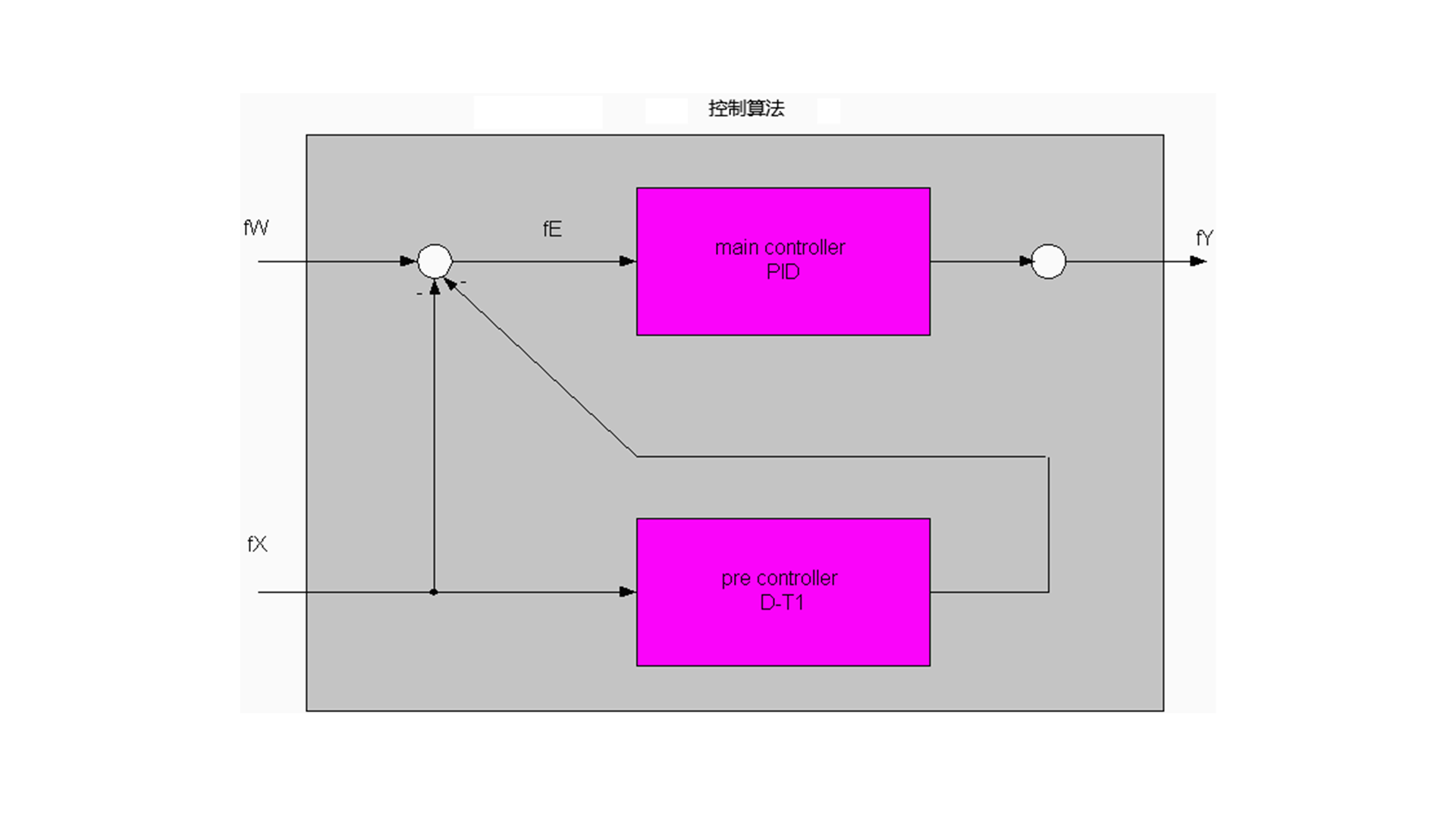
The core of the temperature controller is a standard PID controller. The controller core also supports Anti-Reset Windup measures to constrain the effect of the integral (I) component when the control value is limited. Since the controller adopts the tuning method of Chien, Hrones and Reswick, which is designed to minimize disturbances, overshoot may occur when the setpoint changes.
To reduce this overshoot, a feedforward controller (Pre-Controller) can be inserted to handle setpoint changes. The feedforward controller has D-T1 characteristics, which can reduce the oscillation of the controller overall. However, since the D component of the feedforward controller will cause a "coarsening" effect on the control value, great care must be taken when using the feedforward controller.
When the actual value enters a certain range of the setpoint and remains there for a period of time, the feedforward controller will be turned off. The shutdown of the feedforward controller is completed through a long ramp-down process. To minimize the oscillation of the control value, a filter can also be optionally added after the main controller. Two options are provided for this purpose: P-T1 filter and moving average filter.
Usage Requirements
| Development Environment | Target Platform | Required PLC Library |
|---|---|---|
| MetaFacture | iComputer | ZKSDTempControl |
Alarm
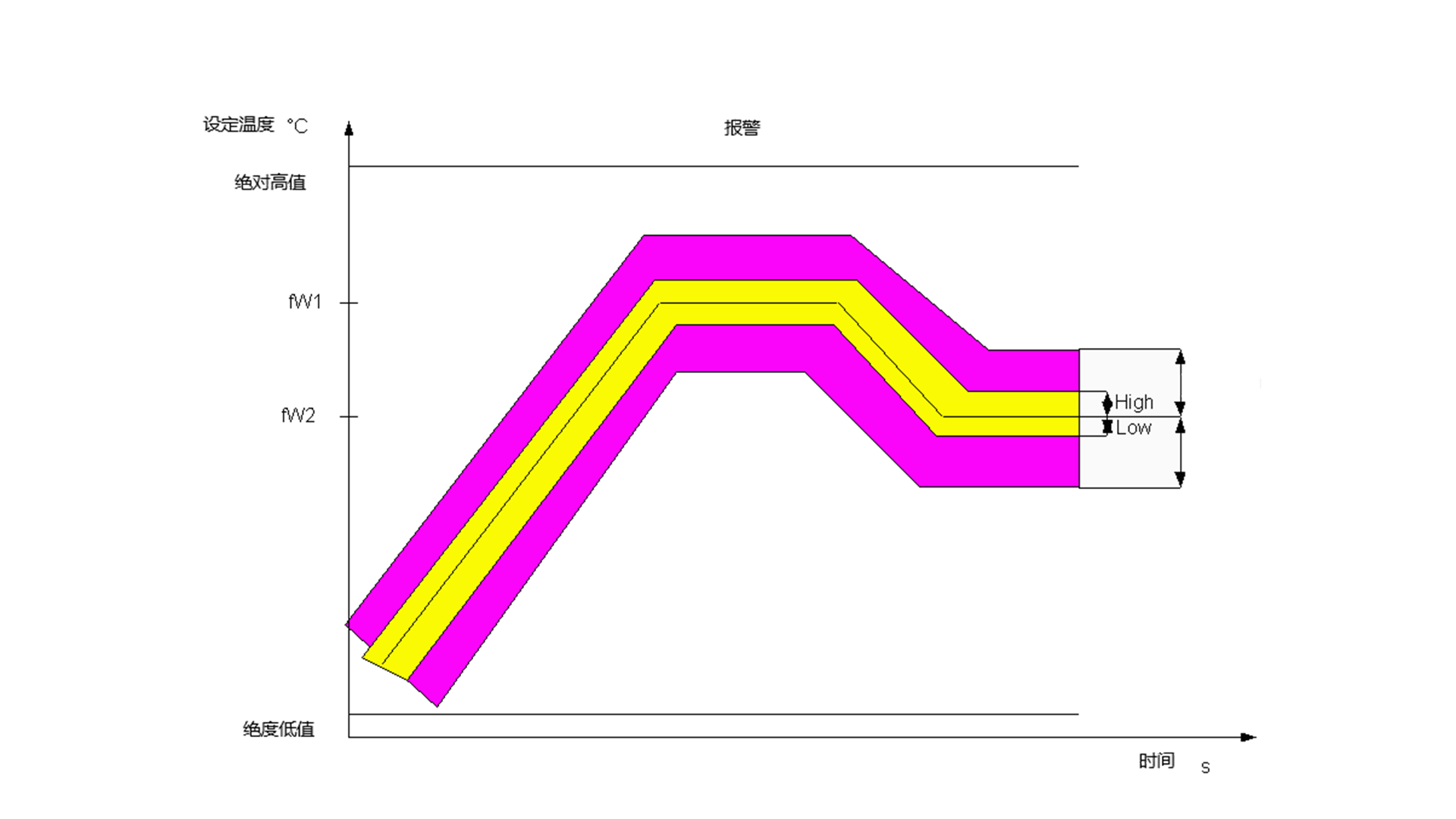
The controller continuously monitors the following alarm conditions:
-
Absolute temperature values (high and low values)
-
Relative temperature values (high and low value bands near the setpoint)
The following sensor-related hardware conditions can also be linked to the temperature controller:
-
Open thermocouple: sensor disconnection
-
Reverse voltage: voltage beyond the allowable range on the sensor
-
Reverse thermocouple wiring
In the case of current-type sensors, the following signals can be connected to the controller:
-
Short circuit
-
Open circuit
-
Leakage current
Usage Requirements
| Development Environment | Target Platform | Required PLC Library |
|---|---|---|
| MetaFacture | iComputer | ZKSDTempControl |
Parameter Self-Tuning
The self-tuning algorithm is based on the classic Inflectional Tangents Method. This method was first proposed by Ziegler and Nichols, assuming that the analyzed system is a linear P-T1 loop with delay time.
In the experimental step, first, the maximum rate of change (Vmax) is determined by observing the difference between several sampling points. Then, a tangent is constructed at the point where the rate of change reaches the maximum, and the intersection of this tangent with the time axis is found. The delay time (Tu) is the time from the start of measurement to the intersection of the inflection tangent with the time axis.
With known Tu and Vmax, the controller parameters can be calculated using the formula proposed by Chien, Hrones and Reswick to achieve disturbance suppression with 20% overshoot. These parameters can also easily derive the parameters of the feedforward controller through heuristic formulas.
After self-tuning is completed, the controller automatically switches to closed-loop operation and uses the calculated parameters for control.
Usage Requirements
| Development Environment | Target Platform | Required PLC Library |
|---|---|---|
| MetaFacture | iComputer | ZKSDTempControl |
Usage and Debugging
The steps to be performed are as follows:
(1) Add the temperature controller library to the project through the library manager
(2) Instantiate at least one temperature controller
-
Create an instance of the controller function block FB_TempController
-
Create an instance of the ST_ControllerParameter structure.
(3) Pin Connection
| Name | Optional | Description |
|---|---|---|
| eCtrlMode | Required | Operation mode: passive, active, check |
| bSelSetpoint | Optional | FALSE = fW1, TRUE = fW2 |
| fW1 | Required | Setpoint |
| fW2 | Optional | Alternative setpoint, generally lower than fW1 |
| fX | Required | Actual value |
| fYManual | Optional | Control value in manual mode |
| bOpenThermocouple | Optional | TRUE: Thermocouple break, hardware feedback signal |
| bReverseThermocouple | Optional | TRUE: Thermocouple wiring error |
| bBackVoltage | Optional | TRUE: Thermocouple wiring error |
| bLeakage | Optional | TRUE: Leakage current detected in heating unit, hardware feedback signal |
| bShortCircuit | Optional | TRUE: Short circuit detected in heating unit, hardware feedback signal |
| bOpenCircuit | Optional | TRUE: Open circuit detected in heating unit, hardware feedback signal |
| sParaControllerExternal | Optional | External controller parameters |
| sControllerParameter | Required | General parameters (sampling time, etc.) |
(4) Parameter initialization, example as follows:
(5) Set the controller sampling time, task cycle, and PWM cycle.
-
The sampling time of the controller is equal to or less than one-tenth of the control cycle.
-
The task cycle depends on the PLC settings. The PWM cycle is usually equal to the controller's cycle time. If the task cycle is 10ms and the PWM cycle is 100ms, there are a total of 10 levels available.
(6) Oscilloscope parameterization
-
Enable the data recording function to record the tuning process and closed-loop control behavior.
-
Monitor the following channels: setpoint (fW1/fW2), actual value (fX), and analog control value (fYAnalog).
(7) Turn off alarms during debugging
-
Alarms can be temporarily turned off during the debugging phase by setting the corresponding bitmask in dwAlarmSupp Dword.
-
If a bitmask is set in the Dword, the corresponding alarm will be turned off. The description of each alarm can be viewed here.
(8) Start controller self-tuning
-
If self-tuning is to be used to determine the controller parameters, the control mode must be set to eCTRL_mode_TUNE.
-
At the beginning, the system will wait for a fixed 20 seconds. During this waiting period, the temperature of this part is monitored to ensure that it remains within the range of ±1°C. If the temperature exceeds this range, the waiting time will be re-timed. Then, the system will apply a step excitation with a control value of fYTune to this part, and this part will respond in the form of a step response. Before reaching 80% of the setpoint, the system uses the inflection tangent method to determine the parameters. For safety reasons, when the temperature reaches 80% of the setpoint, the system switches to closed-loop control mode. If the temperature reaches the 80% mark too quickly (without a clear inflection point), the value of fYTune needs to be reduced. The parameters determined by the above method will be used for the PID controller and provided in the structure at the controller output.
(9) Connect internal control parameters with external connections
-
The controller parameters determined during the tuning process can be provided to the controller again as external parameters. This may be necessary in some cases, for example, when tuning is performed only once during initial commissioning.
-
To do this, feed back the sParaControllerInternal structure to the sParaControllerExternal input of the controller, and set the bSelCtrlParameterSet flag to TRUE.
(10) Manual fine-tuning
The control parameters determined during the tuning process are designed to achieve fast stabilization, usually with about 10% overshoot. If only minimal or no overshoot is allowed, the following parameters in the ST_ControllerParameter structure can be used for fine-tuning. These values are provided for reference only.
| Behavior | fTuneKp | fTuneTn | fTuneTv | fTuneTd |
|---|---|---|---|---|
| Fast setting, 10%-20% overshoot | 1.2 | 2.0 | 0.42 | 0.25 |
| Slower setting, less overshoot | 1.0 | 2.5 | 0.42 | 0.25 |
| Slow adjustment, almost no overshoot | 0.5 | 3.0 | 1.0 | 0.25 |
Usage Requirements
| Development Environment | Target Platform | Required PLC Library |
|---|---|---|
| MetaFacture | iComputer | ZKSDTempControl |