SF512x Kinematics Transformer
Overview
SF512x Kinematics Transformer
This product is a high-performance kinematic transformation tool designed for industrial automation applications, integrating robot control and traditional PLC into a single system. By implementing the entire control function within the same system, it eliminates performance losses caused by different CPU interfaces between PLC, motion control, and robot control.
This product provides high-precision forward and inverse kinematics calculation functions, supporting precise position and attitude control of 4D-SCARA robots in complex working environments. Through parameterized design, it supports various robot configurations, including arm length, angle range, load capacity, etc., to adapt to different work requirements.
Overview of Coordinate Systems
Coordinate systems are essential when describing the motion and position behavior of a system. The following are several commonly used coordinate systems and their characteristics:
-
Machine Coordinate System (MCS) is a Cartesian coordinate system based on the robot, usually with its origin located on the robot's base.
-
World Coordinate System (WCS) is a Cartesian coordinate system describing the entire modeling "world" and has no direct association with a specific robot. The origin of the robot's Machine Coordinate System (MCS) is located at a specific point in the World Coordinate System, and users can define the position and orientation of the robot in the "world". A WCS can contain multiple robots. When using a robot, the World Coordinate System and the Machine Coordinate System can coincide to improve transparency.
-
Program Coordinate System (PCS) can be set at any position and in any direction within the World Coordinate System. It is suitable for complex working environments, such as scenarios involving multiple work areas or multiple workpiece operations.
-
Axis Coordinate System (ACS) describes the motion position of the robot's physical axes and is usually not a Cartesian coordinate system. Many robot joint axes mainly perform rotational motion, so the Axis Coordinate System is more suitable for describing the limit values of rotation angles, speeds, and accelerations. The Axis Coordinate System is usually used for reference point positioning (reference/homing operations).
Coordinate Transformation in Kinematics
In industrial robot programming, the Machine Coordinate System (MCS) is usually taken as the basis. Since humans more intuitively use Cartesian coordinate systems (such as X, Y, Z axes) for thinking and planning, it is necessary to perform coordinate conversion between the Axis Coordinate System (ACS) and the Cartesian space when executing motions.
Transformation in kinematics describes the calculation process required to switch from one coordinate system to another. Coordinate transformations in robot kinematics mainly involve the following two situations:
-
Forward transformation refers to the conversion from the Axis Coordinate System (ACS) to the Cartesian coordinate system. The Cartesian position of the Tool Center Point (TCP) is calculated based on the robot's axis-specific joint coordinates.
-
Inverse transformation refers to the conversion of the TCP position in the Cartesian coordinate system to the Axis Coordinate System (ACS). To drive the actual motion of the robot, it is necessary to convert the desired TCP position and attitude into the axis coordinate parameters of each joint.
4D-SCARA Robot (S_CCZC)
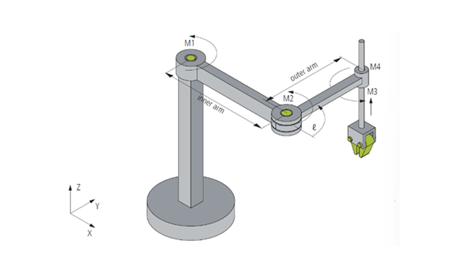
The 4D-SCARA (Selective Compliance Assembly Robot Arm) is a robot with four degrees of freedom (DOF), whose kinematic structure and motor axis configuration are shown in the figure. Motor axes M1, M2, and M4 are rotary axes with the unit of degrees (°), and the arrows indicate their positive rotation directions. The third motor axis M3 is a linear axis with the unit of millimeters (mm), used to realize vertical motion.
The origin of the Machine Coordinate System (MCS) is located at the first joint (M1). When all rotary motor axes (M1, M2, M4) are at 0°, the direction pointed by the SCARA arm is the X-axis. This configuration defines the X-axis direction of the MCS. The Y-axis is perpendicular to the X-axis, forming a right-hand Cartesian coordinate system, and the Z-axis is in the vertical direction, consistent with the linear motion of M3.
This configuration ensures high-precision path planning and motion control, and provides a foundation for the robot's efficient performance in industrial tasks.
Installation and Uninstallation
Installation Requirements
This section describes the minimum requirements for the engineering and/or runtime system.
1. Hardware Requirements
Devices supporting the MetaFacture platform (PLC or embedded systems).
2. Software Requirements
Installed MetaFacture development environment.
Operating system support: MetaOS or other compatible platforms.
Relevant library or module dependencies must be available (such as basic I/O libraries).
Installation Process
1. Installation via Library Manager
Open the engineering project in MetaFacture.
Select "Tools" -> "Library Storage" through the menu.

Click Install and open the Kinematics library file.
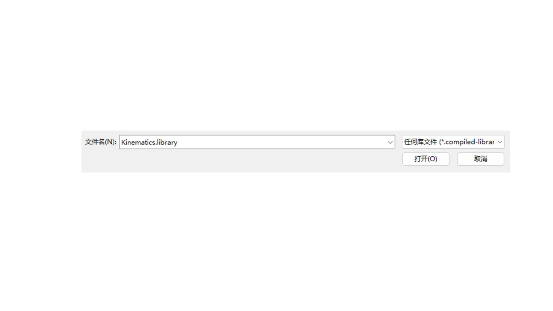
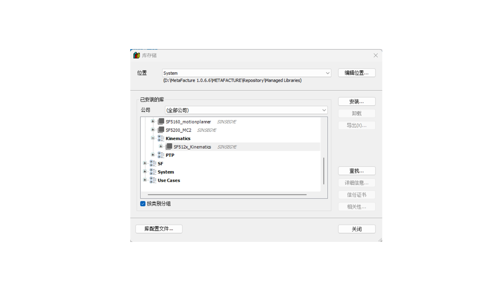
After successful opening, close the window.
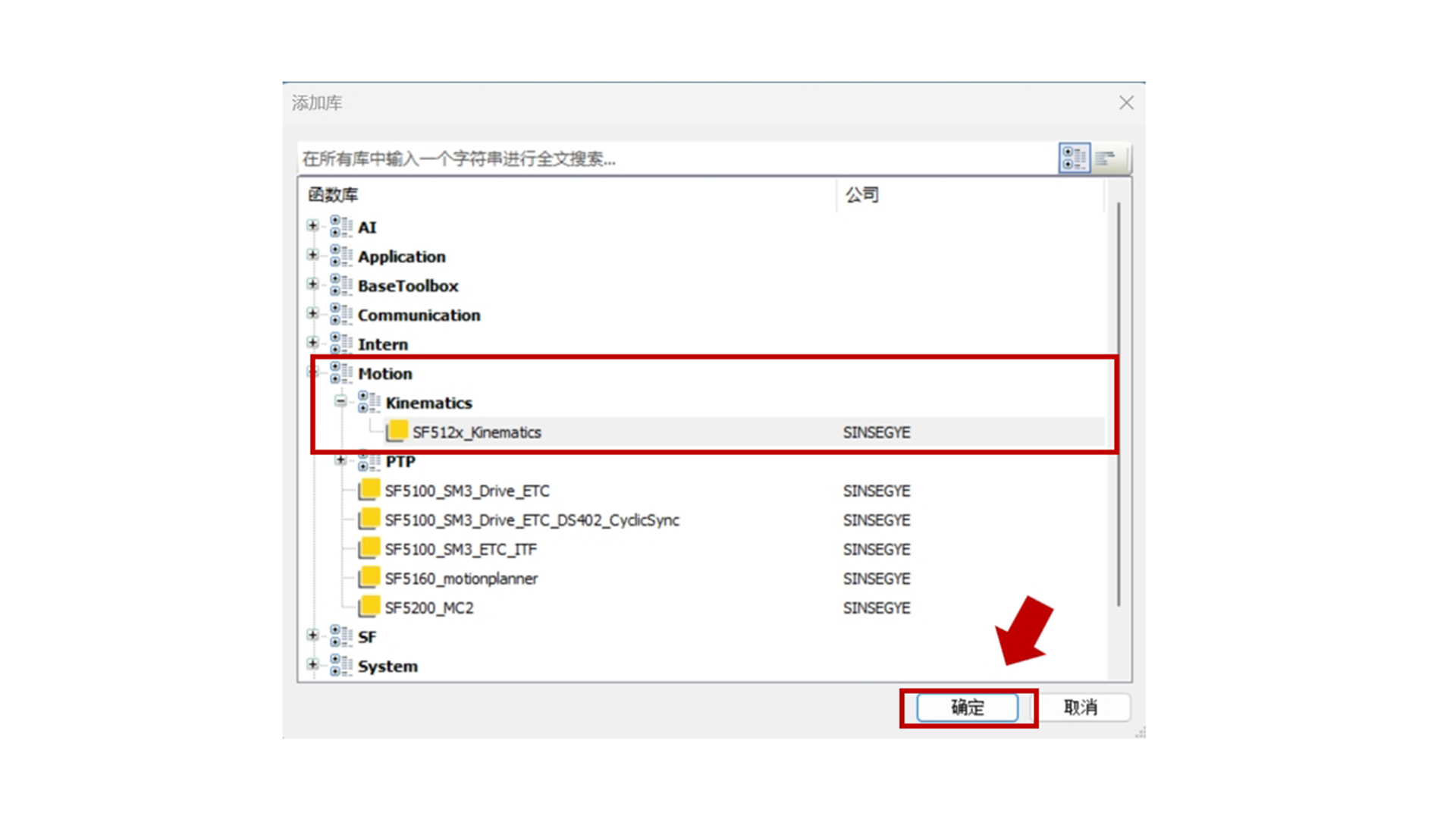
Click "Add Library"
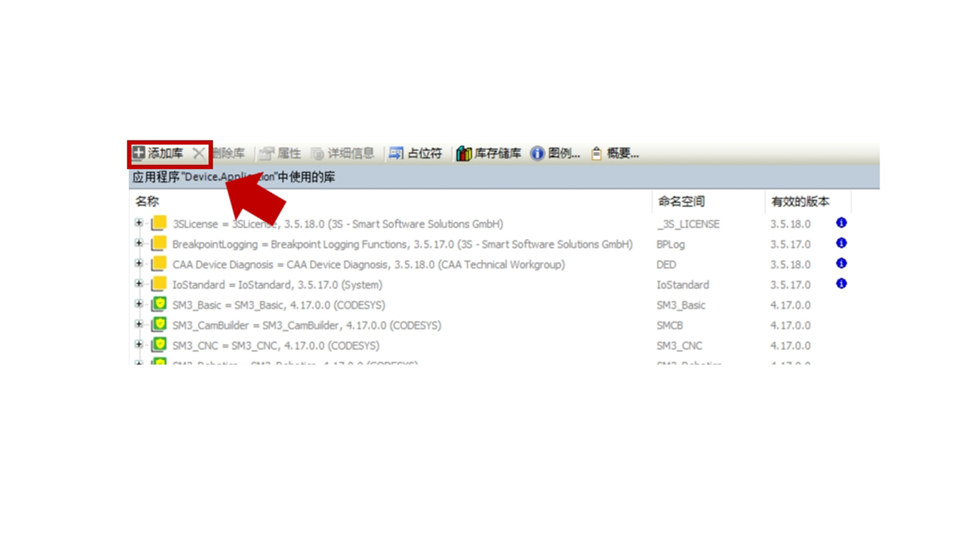
Select Kinematics and click Confirm.
Update Installation
1. Overwrite Installation
Download the latest version of the Kinematics library file.
Open the MetaFacture project, delete the old version of the library in the "Library Manager", and import the new version of the library file.
Save the project and recompile.
2. Version Compatibility Verification
Check whether the new version is compatible with the existing project.
Adjust possible differences between the old and new versions according to the documentation.
Uninstallation Process
1. Uninstallation via Library Manager
Open the MetaFacture project and enter the "Library Manager".
Select the Kinematics library and click "Delete Library" to uninstall the library file.
- Clean Up Project Dependencies
Open the engineering project, check and remove all function blocks or interfaces that use the Kinematics library.
Ensure that there are no errors when the project is recompiled.